Wavelength variable light source apparatus

Inactive Publication Date: 2003-10-30
ANDO ELECTRIC CO LTD
View PDF6 Cites 2 Cited by
  • Summary
  • Abstract
  • Description
  • Claims
  • Application Information

AI Technical Summary

Problems solved by technology

As a result, there is a problem in which the wavelength variable light source apparatus 300 is upsized.
Furthermore it is u

Method used


Image

  • Wavelength variable light source apparatus
  • Wavelength variable light source apparatus
  • Wavelength variable light source apparatus

Examples


first embodiment

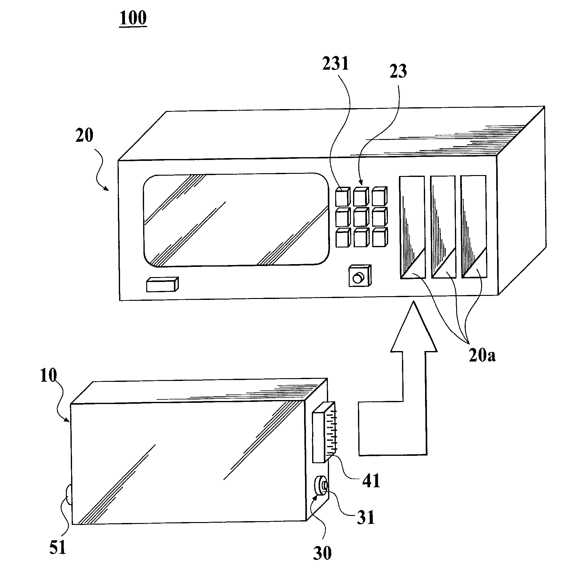
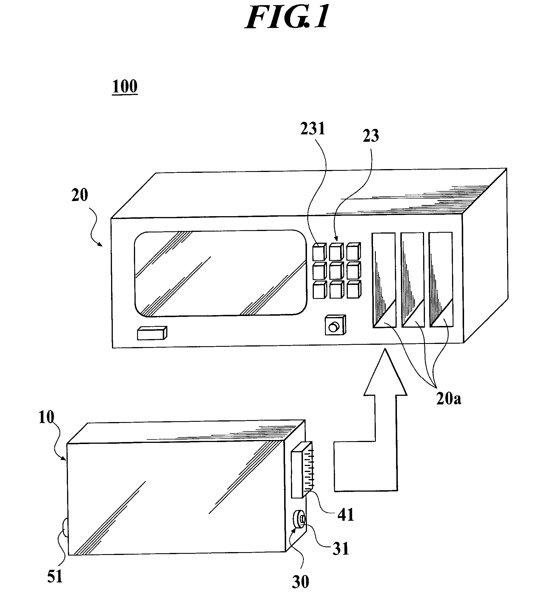
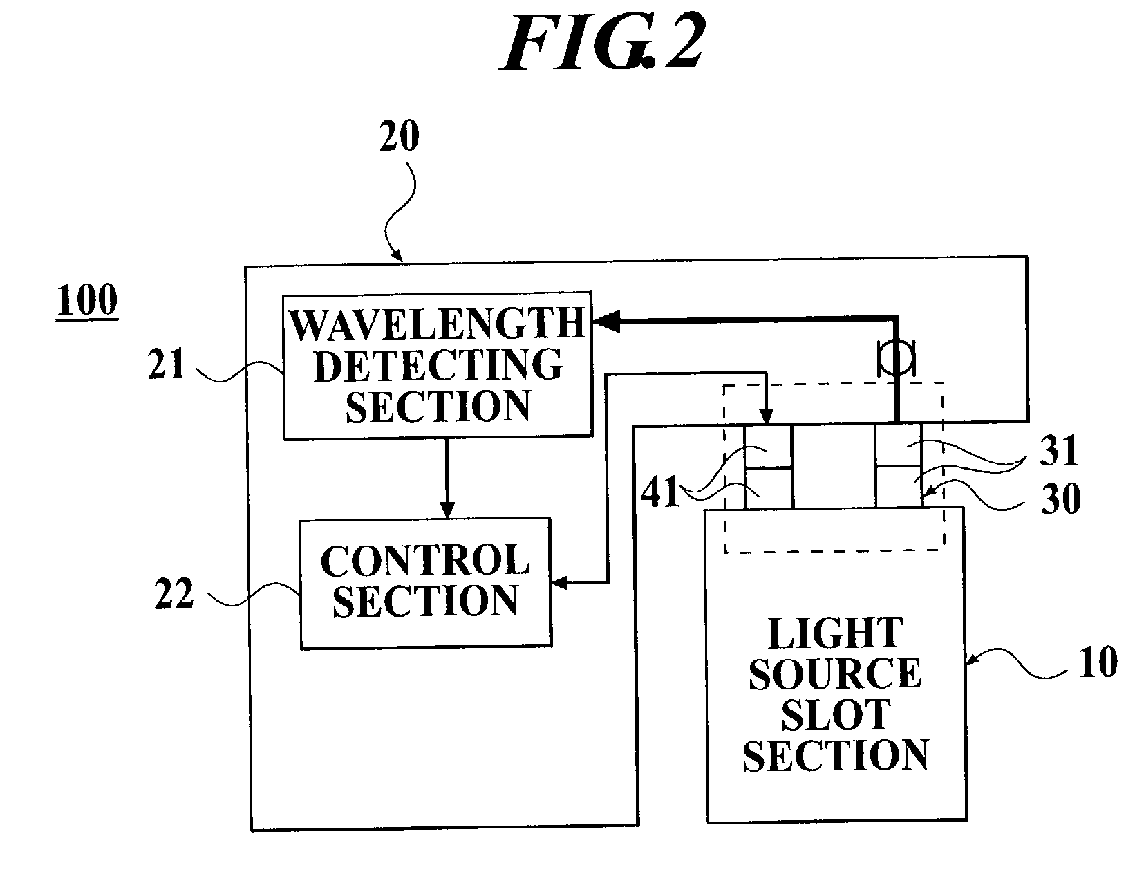
[0034] FIG. 1 shows a prospective view of a wavelength variable light source apparatus according to the present invention. FIG. 2 is a block diagram for illustrating a brief configuration of the wavelength variable light source apparatus. FIG. 3 is a block diagram for illustrating a functional configuration of the wavelength variable light source apparatus.

[0035] As shown in FIGS. 1 and 2, a wavelength variable light source apparatus 100 of the present invention comprises a light source slot section 10 for generating a laser light and a main control section 20 connected to the light source slot section 20 which is inserted into the main control section 20. The main control section 20 is for optionally varying the wavelength and the output level of the laser light which is outputted from the light source slot section 10.

[0036] The main control section 10 comprises a plurality of plug sections 20a with a predetermined interval. The light source slot section 10 is selectively inserted ...

second embodiment

[0064] FIG. 4 is a block diagram for illustrating a brief configuration of a wavelength variable light source apparatus according to the present invention.

[0065] As shown in FIG. 4, a wavelength variable light source apparatus 100a of the present invention is different from the wavelength variable light source apparatus 100 of the first embodiment. In the wavelength variable light source apparatus 100a, the above-mentioned optical connecting mechanism 30 becomes a non-contact connection state by a spatial light. More particularly, an optical collimator is used which converts the light outputted from the optical fiber, into the parallel light by a lens 33.

[0066] Incidentally, the parts which are similar to the first embodiment will be designated by same reference numerals in the FIG. 4 and the description will be omitted.

[0067] According to the second embodiment of the present invention, it is possible to avoid the mechanical fracture when the light source slot section 10 is connecte...

third embodiment

[0068] FIG. 5 is a block diagram for illustrating a brief configuration of a wavelength variable light source apparatus according to the present invention.

[0069] As shown in FIG. 5, a wavelength variable light source apparatus 100b of the present invention comprises a plurality of light source slot sections 10 which generate laser lights having wavelengths different from one another. The light source slot sections 10 are inserted into the plug sections 20a of the main control section 20, respectively. The light source slot sections 10 are connected to the main control section 20 by the optical connecting mechanisms 30 and the electric connectors 41. In addition, the main control section 20 comprises the wavelength compensating section composed of the wavelength detecting section 21 and the control section 22 described in conjunction with the first embodiment.

[0070] Incidentally, each of the optical connecting mechanisms 30 may be the above-mentioned light connectors 31 or the optica...


PUM


Abstract

In order to provide a wavelength variable light source apparatus capable of easily introducing a laser light outputted from a light source slot section, into a main control section, the wavelength variable light source apparatus comprises the light source slot section for generating the laser light and the main control section into which the light source slot section is inserted and which is connected to the light source slot section. The main control section optionally varies a wavelength and an output level of the laser light which is outputted from the light source slot section. An optical connecting mechanism is installed at a connecting section between the light source slot section and the main control section. The optical connecting mechanism supplies the main control section with a part of laser light which is outputted from the light source slot section.

Description

[0001] 1. Field of the Invention[0002] The present invention relates to a wavelength variable light source apparatus for use in optical measurement technical field or the like.[0003] 2. Description of the Related Art[0004] As shown in FIG. 7, a wavelength variable light source apparatus 300 comprises a plurality of light source slot sections 301 and a main control section 302 (only one light source slot section is illustrated in FIG. 7). The light source slot sections 301 generate laser lights which have wavelength variable ranges different from one another, respectively. A selected one of the light source slot sections 301 may be inserted in one of plug sections 302a which are installed in the main control section 302, according to intended use.[0005] The light source slot section 301 inserted in one of the plug sections 302a is connected to the main control section 302 through an electric connector 303 for use in control (communication) on optionally varying the wavelength and out...

Claims


Application Information

Patent Timeline
IPC IPC(8): H01S5/0687H01S5/14G02B5/18
CPCH01S5/0687H01S5/143H01S5/141
Inventor TAKAI, HIRONORI
Owner ANDO ELECTRIC CO LTD
Why Eureka
Try Eureka