
Sealed mixer

a technology of sealer and hopper, which is applied in the direction of mixing, mechanical equipment, chemistry equipment and processes, etc., can solve the problems of cumbersome lubricant supply operation in the hopper, and achieve the effect of convenient supply of lubrican

Active Publication Date: 2012-01-26
KOBE STEEL LTD
View PDF3 Cites 2 Cited by
  • Summary
  • Abstract
  • Description
  • Claims
  • Application Information

AI Technical Summary

Benefits of technology

[0006]Another object of the present invention is to provide a sealed mixer capable of easily supplying lubricant to a weight.

Problems solved by technology

Further, the lubricant supplying operation in a hopper has been very cumbersome.

Method used


Image

  • Sealed mixer
  • Sealed mixer
  • Sealed mixer

Examples


Embodiment Construction

[0016]Hereinafter, an embodiment of the present invention is described with reference to the drawings.

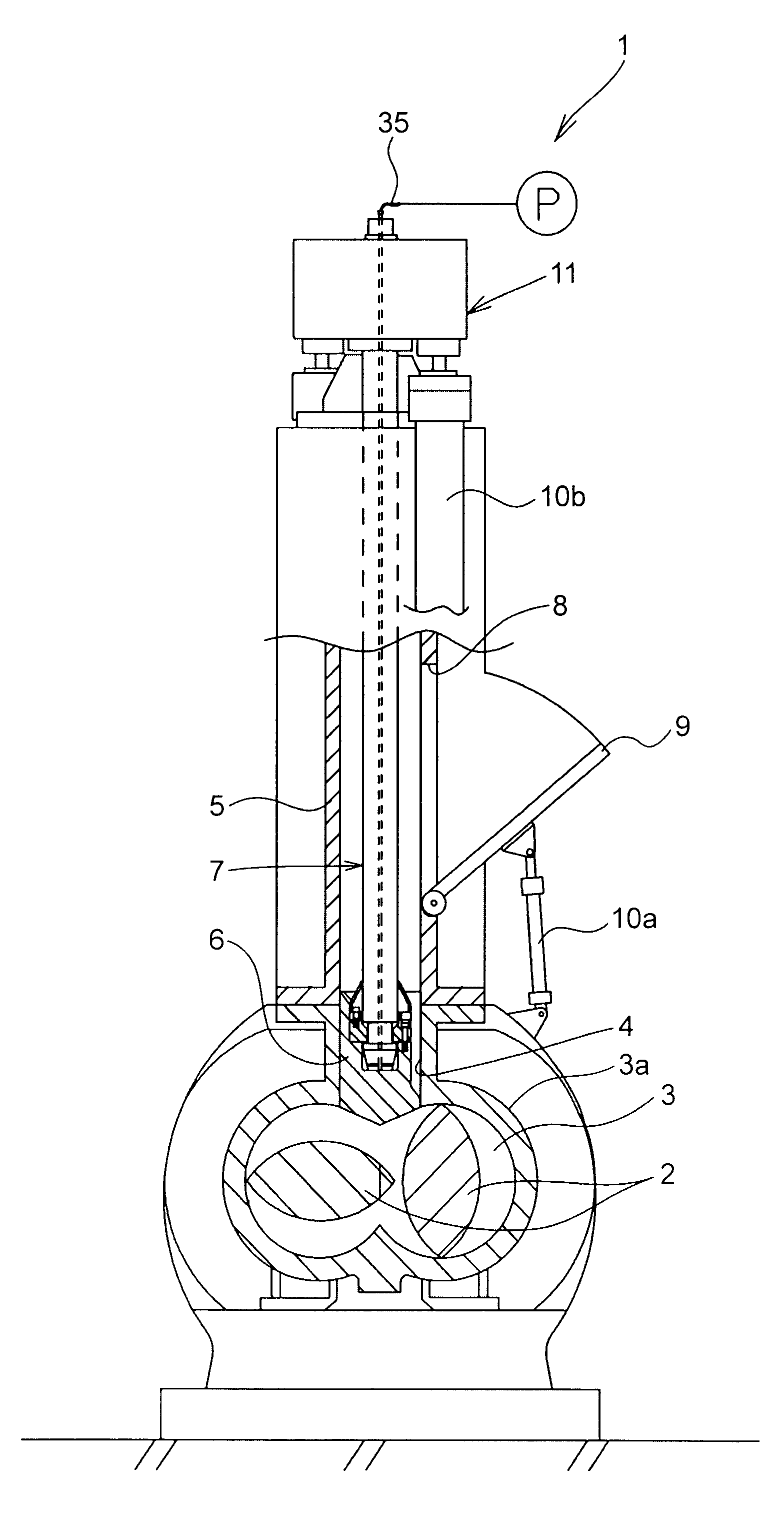
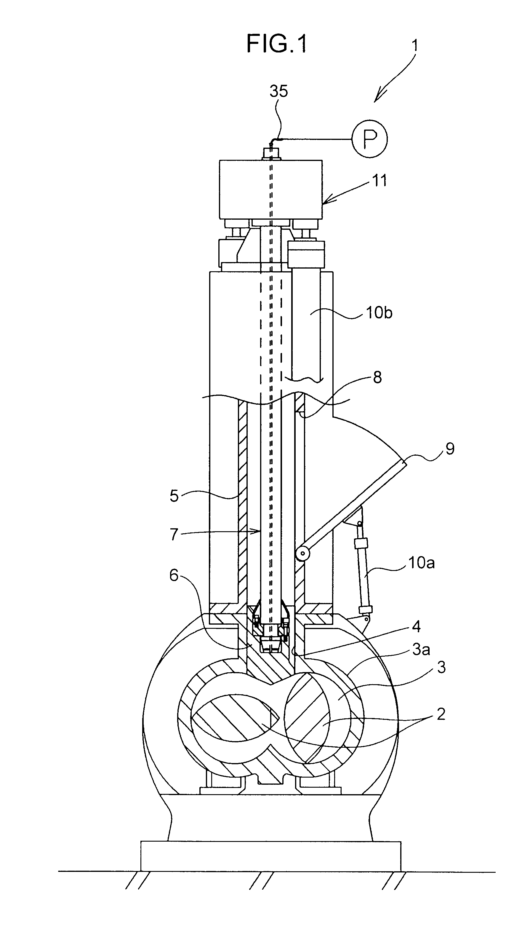
[0017]First, the overall construction of a sealed mixer 1 according to one embodiment of the present invention is described with reference to FIG. 1.

[0018]The sealed mixer 1 of this embodiment is a batch mixer for forcibly pressing materials such as rubber and plastic into a mixing chamber 3 and mixing these materials by mixing rotors 2 which rotate in the mixing chamber 3. This sealed mixer 1 includes a pair of mixing rotors 2, a housing 3a, a hopper 5, a weight 6, a shaft member 7, a hopper door 9 and a hydraulic cylinder 10a.

[0019]The mixing chamber 3 in which the pair of left and right mixing rotors 2 are rotatably arranged is provided in the housing 3a. The mixing chamber 3 is in the form of a hole having a spectacle-shaped cross-section along a plane perpendicular to axial directions of the mixing rotors 2. That is, the mixing chamber 3 is formed to have such a shape that a p...


PUM

PropertyMeasurementUnit
weightaaaaaaaaaa
shapeaaaaaaaaaa
floating weightaaaaaaaaaa

Abstract

A sealed mixer comprises a housing provided with a mixing chamber and a material insertion port for inserting materials into the mixing chamber; a weight for pressing the materials inserted into the material insertion port toward the mixing chamber; and a shaft member which extends upward from the weight and moves upward and downward together with the weight, the weight being connected to a lower end portion of the shaft member, a reservoir adapted to store lubricant between the weight and the shaft member is formed at a part connecting the weight and the shaft member, and a lubricant supply path adapted to supply the lubricant from an outside toward the reservoir is formed in the shaft member.

Description

TECHNICAL FIELD[0001]The present invention relates to a sealed mixer with a weight, for example, for pressing materials inserted into the mixer toward a mixing chamber.BACKGROUND ART[0002]Conventionally, a sealed mixer disclosed in patent document 1 has been, for example, known as the one with a weight for pressing materials inserted into the mixer toward a mixing chamber. Patent document 1 discloses the sealed mixer including a floating weight provided movably upward and downward and capable of pressing materials toward a mixing chamber of a mixer main body, and a shaft member connected to the floating weight and extending in an elevation direction of the floating weight. In such a sealed mixer, lubricant such as grease for easing friction and the like between the floating weight and the shaft member is generally filled in the floating weight.[0003]In the sealed mixer as disclosed in patent document 1, to replace the lubricant in the floating weight and fill the lubricant into the ...

Claims


Application Information

Patent Timeline
Patent Type & Authority Applications(United States)
IPC IPC(8): B01F15/02
CPCB29B7/183F16N7/38F16N1/00B29B7/246B29B7/22B29B7/18B29B7/24
Inventor NAOI, MASAKIKUBO, KENJI
Owner KOBE STEEL LTD
Learn More