Liquid ejection head and liquid ejection apparatus

a liquid ejection head and liquid ejection technology, applied in the direction of printing, inking apparatus, etc., can solve the problems of image quality degradation, significant performance difference between head chips, etc., and achieve the effect of small variation in ejection characteristics, easy supply of liquid, and small variation in ejection speed

Inactive Publication Date: 2008-02-26
SONY CORP
View PDF5 Cites 3 Cited by
  • Summary
  • Abstract
  • Description
  • Claims
  • Application Information

AI Technical Summary

Benefits of technology

[0023](3) The results are an increase in cost and a reduction in production yield.
[0029]The present invention provides the following advantages. That is, one advantage is the ability to equally supply liquid to respective liquids. Another advantage is a small variation in ejection characteristics among liquid ejection elements. For example, it is possible to achieve a very small variation in terms of ejection speed among liquid ejection elements. Furthermore, it is possible to easily supply liquid to respective liquid chambers, and it is possible to suppress the probability of occurrence of a failure due to a bubble to an extremely low level. Even if a failure due to a bubble occurs, self-recovering from the failure can easily occur.

Problems solved by technology

In particular, in a case in which a line head with a length equal to the width of a recording medium is produced by arraying a plurality of head chips 1a on the nozzle sheet 17, a slight change in a production condition can cause a significant difference in performance among head chips 1a, which can result in degradation in image quality.
However, this structure has the following problems.

Method used


Image

  • Liquid ejection head and liquid ejection apparatus
  • Liquid ejection head and liquid ejection apparatus
  • Liquid ejection head and liquid ejection apparatus

Examples


examples

[0180]Specific examples are described below.

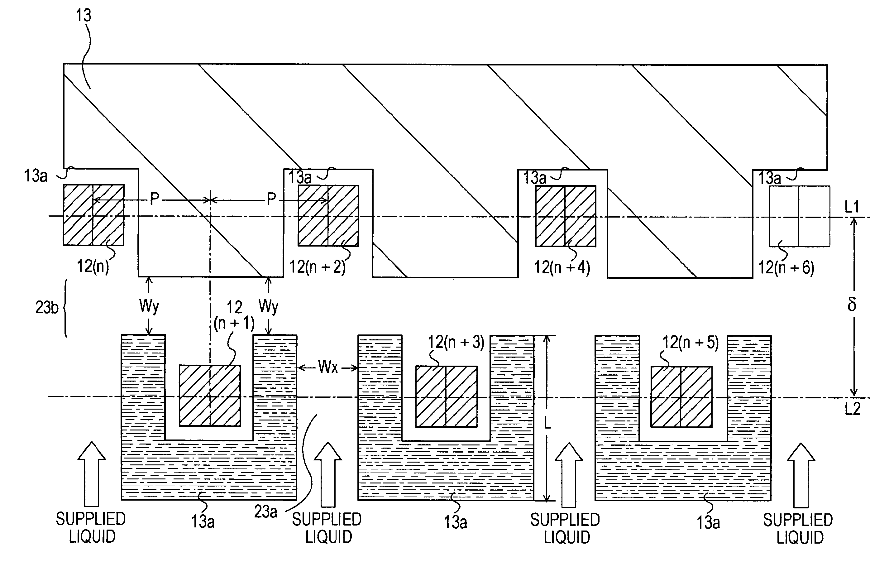
[0181]FIG. 10 shows a part of a semiconductor processing mask according to an embodiment of the present invention. In the example shown in FIG. 10, the semiconductor processing mask is designed so as to produce liquid chambers 13a with a symmetric shape such as those shown in FIG. 5 and so as to produce rectangular-column filters 30 at regular intervals of 2P at locations corresponding to the locations of respective liquid chambers 13a disposed in a lower line in FIG. 10. In FIG. 10, liquid is supplied from the upper side (where filters 30 are disposed), and the barrier layer 13 is located on the lower side. In the mask pattern shown in FIG. 10, locations of the heating element 12s are additionally shown by dotted lines. The intervals P of heating element 12s are set to 42.3 μm to obtain a resolution of 600 DPI. In FIG. 10, the distance (corresponding to δ in FIG. 3 or 4) in the vertical direction between two adjacent center lines of the a...


PUM


Abstract

A liquid ejection head includes a plurality of liquid ejection elements arrayed in a flat area on a substrate. Each liquid ejection element includes a liquid chamber, a heating element disposed in the liquid chamber, and a nozzle. The heating elements are disposed alternately on a first and second lines spaced by δ in a zigzag fashion. Each liquid chamber is formed to have a U-like shape in horizontal cross section such that a wall thereof surrounds three sides of a heating element disposed in each liquid chamber. A gap Wx is formed between each two adjacent liquid chambers located on the second line, and a gap Wy is formed between the liquid chambers located on the first line and the liquid chambers located on the second line. The gaps Wx serve as first common flow channels, and the gap Wy serves as a second common flow channel.

Description

CROSS REFERENCES TO RELATED APPLICATIONS[0001]The present invention contains subject matter related to Japanese Patent Application JP 2004-260449 filed in the Japanese Patent Office on Sep. 8, 2004, the entire contents of which are incorporated herein by reference.BACKGROUND OF THE INVENTION[0002]1. Field of the Invention[0003]The present invention relates to a thermal liquid ejection head used in an ink-jet printer head or the like, and also to a liquid ejection apparatus such as an ink-jet printer using a liquid ejection head. More specifically, the present invention relates to a technique to realize a structure for supplying liquid with minimized ejection variations.[0004]2. Description of the Related Art[0005]One known liquid ejection head for use in a liquid ejection apparatus such as an ink-jet printer is a thermal liquid ejection head which operates using expansion and contraction of a generated bubble.[0006]In this thermal liquid ejection head, heating elements are disposed ...

Claims


Application Information

Patent Timeline
Patent Type & Authority Patents(United States)
IPC IPC(8): B41J2/05
CPCB41J2/1404B41J2/14056B41J2/14145B41J2202/20B41J2002/14387B41J2/05B41J2/16
Inventor EGUCHI, TAKEOONO, SHOGOMIYAMOTO, TAKAAKITAKENAKA, KAZUYASU
Owner SONY CORP
Why Eureka
Try Eureka