Method of controlling temperature/humidity or temperature and device for controlling temperature/humidity or temperature

a technology of temperature/humidity or temperature and control device, which is applied in the direction of domestic cooling apparatus, heating types, instruments, etc., can solve the problems of increasing energy consumption, increasing energy consumption, and waste of energy, and achieves the effect of minimizing output cancellation and saving energy

Inactive Publication Date: 2005-05-31
YAMATAKE HONEYWELL CO LTD
View PDF5 Cites 21 Cited by
  • Summary
  • Abstract
  • Description
  • Claims
  • Application Information

AI Technical Summary

Benefits of technology

[0007]The present invention has been made to solve the above problems, and has as its object to provide a method of controlling temperature/humidity or temperature and device for contr

Problems solved by technology

If this output cancellation is inappropriately performed, however, energy is wasted.
This increases the energy co

Method used


Image

  • Method of controlling temperature/humidity or temperature and device for controlling temperature/humidity or temperature
  • Method of controlling temperature/humidity or temperature and device for controlling temperature/humidity or temperature
  • Method of controlling temperature/humidity or temperature and device for controlling temperature/humidity or temperature

Examples


first embodiment

[First Embodiment]

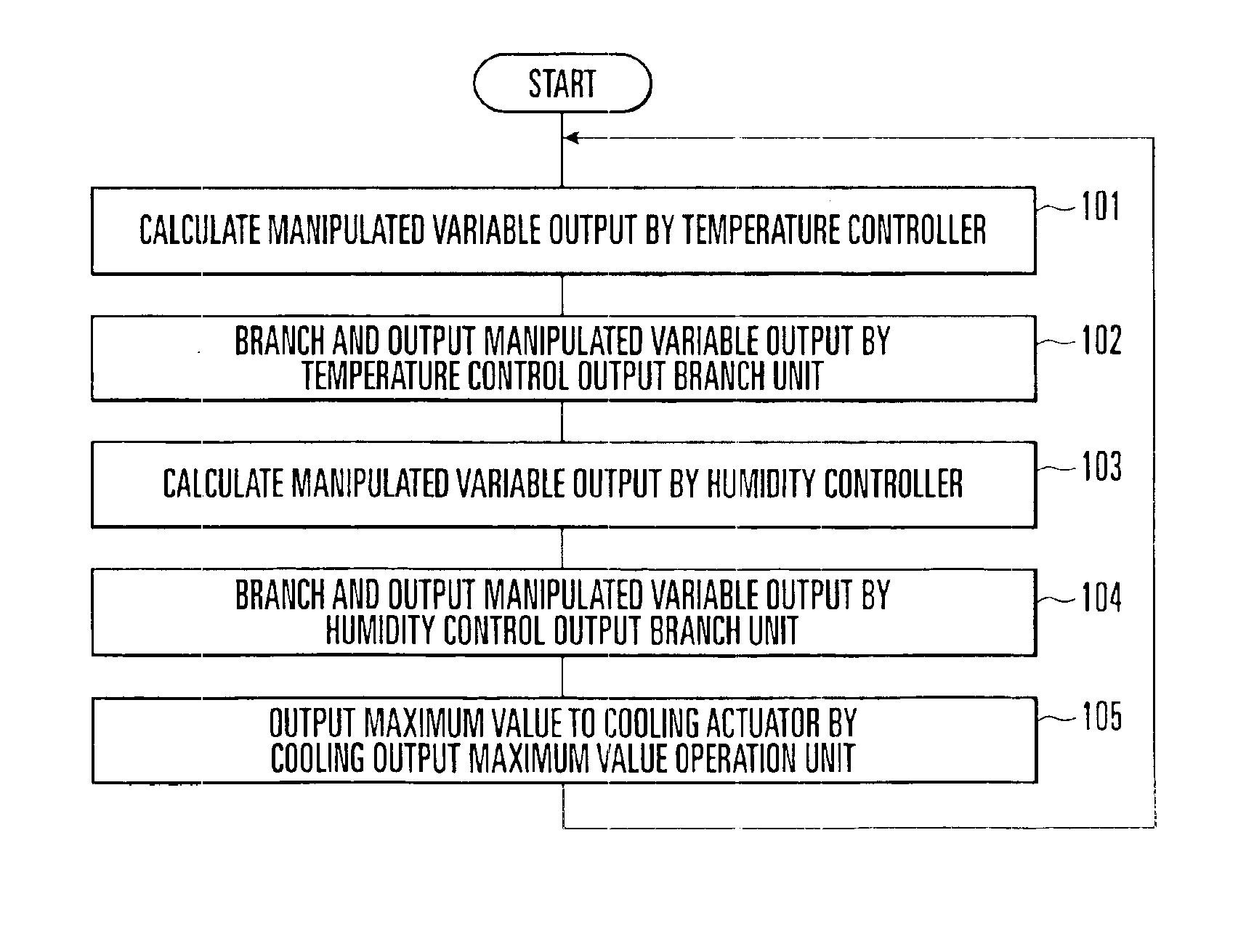
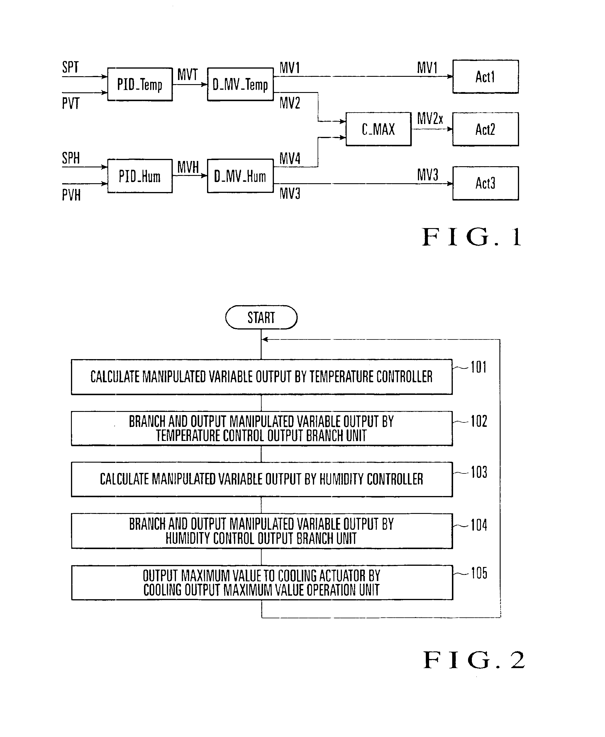
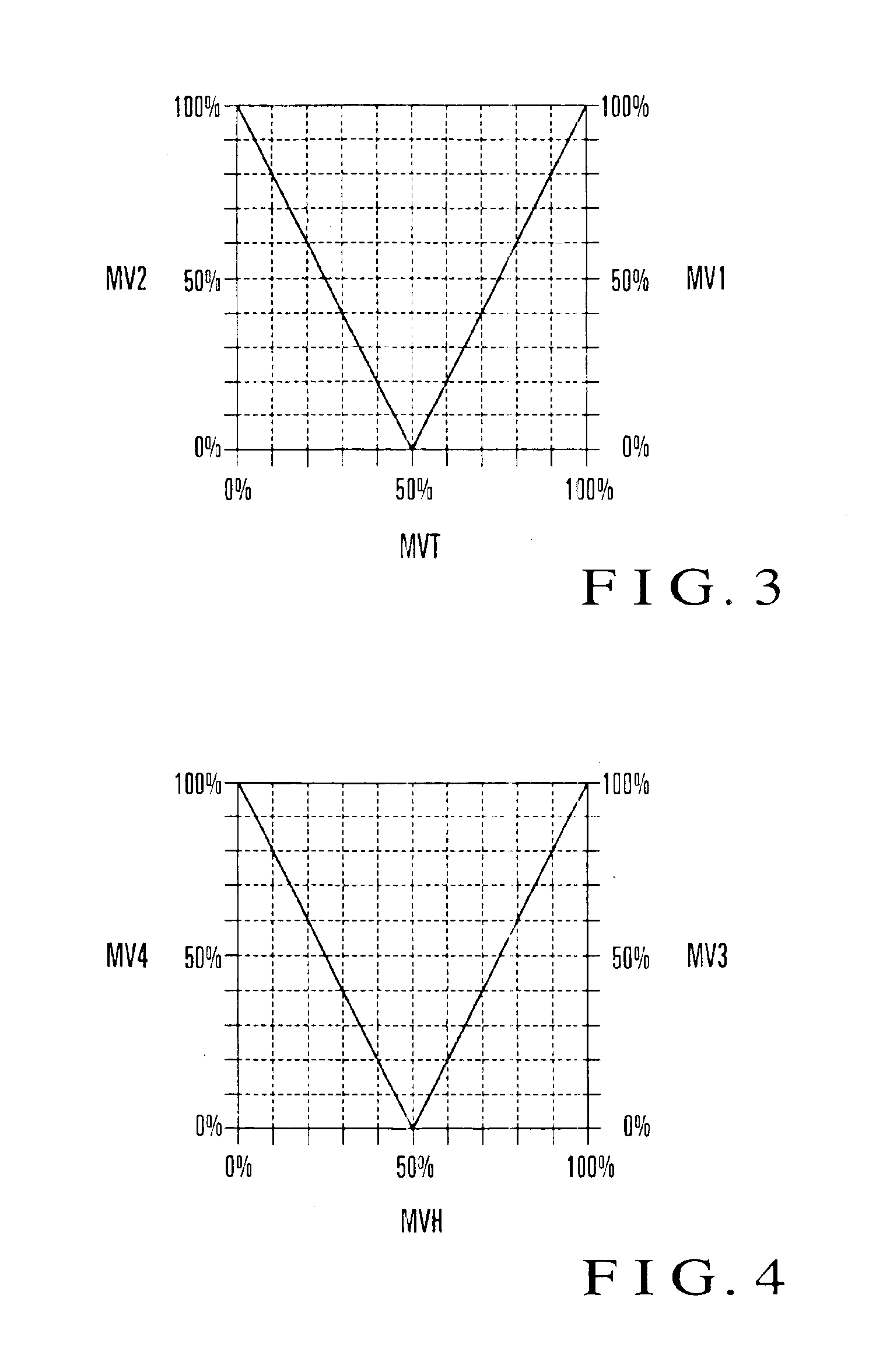
[0024]An embodiment of the present invention will be described in detail below with reference to the accompanying drawings. FIG. 1 is a block diagram showing the arrangement of a temperature / humidity control device as the first embodiment of the present invention. This temperature / humidity control device shown in FIG. 1 comprises a temperature controller PID_Temp for controlling temperature, a humidity controller PID_Hum for controlling humidity, a temperature control output branch unit D_MV_Temp for branching and outputting a manipulated variable output MVT from the temperature controller PID_Temp, a humidity control output branch unit D_Mv_Hum for branching and outputting a manipulated variable output MVH from the humidity controller PID_Hum, a cooling output maximum value operation unit C_MAX for comparing the manipulated variable outputs from the temperature control output branch unit D_MV_Temp and humidity control output branch unit D_MV_Hum and giving the lar...

second embodiment

[Second Embodiment]

[0057]FIG. 5 is a block diagram showing the arrangement of a temperature / humidity control device as the second embodiment of the present invention. The same reference numerals as in FIG. 1 denote the same parts. This temperature / humidity control device shown in FIG. 5 comprises a heating temperature controller PID_Temp1 for controlling heating, a cooling temperature controller PID_Temp2 for controlling cooling, a humidifying humidity controller PID_Hum3 for controlling humidifying, a dehumidifying humidity controller PID_Hum4 for controlling dehumidification, a temperature controller switching unit CH_Temp for switching the controllers PID_Temp1 and PID_Temp2, a humidity controller switching unit CH_Hum for switching the controllers PID_Hum3 and PID_Hum4, a cooling output maximum value operation unit C_MAX, a heating actuator Act1, a cooling actuator Act2, and a humidifying actuator Act3.

[0058]An object of this embodiment is an air-conditioning control system. For...

third embodiment

[Third Embodiment]

[0064]FIG. 6 is a block diagram showing the arrangement of a temperature control device as the third embodiment of the present invention. This temperature control device shown in FIG. 6 comprises a heating temperature controller PID_H for controlling heating, a heating temperature controller PID_H which receives a manipulated variable output from the heating temperature controller PID_H as a controlled variable input and performs an operation by using an ideal value of the manipulated variable output as a set point, a cooling temperature controller PID_C, a heating actuator Act1 such as a heater, and a cooling actuator Act2 such as a cooler.

[0065]This embodiment can be applied to a temperature control system for a pre-cooling / re-heating type temperature controlled bath using a cooler and heater, when energy saving is to be realized by suppressing output cancellation of a heating / cooling function.

[0066]The operation of the temperature control device of this embodime...


PUM


Abstract

A temperature control output branch unit D_MV_Temp outputs a manipulated variable to a heating actuator Act1 when the manipulated variable output MVT of a temperature controller PID_Temp is in a heating mode, and outputs it to a cooling actuator Act2 when the output MVT is in a cooling mode. A humidity control output branch unit D_MV_Hum outputs a manipulated variable to a humidifying actuator Act3 when the manipulated variable output MVH of a humidity controller PID_Hum is in a humidifying mode, and outputs it to the actuator Act2 when the output MVH is in a dehumidifying mode. A cooling output maximum value operation unit C_MAX gives whichever is larger of respective manipulated variable outputs from the branch units D_MV_Temp and D_MV_Hum to the actuator Act2.

Description

[0001]The present patent application is a non-provisional application of International Application No. PCT / JP01 / 06732, filed Aug., 6, 2001.BACKGROUND OF THE INVENTION[0002]The present invention relates to a method of controlling temperature / humidity or temperature and device for controlling temperature / humidity or temperature which can realize energy saving in a temperature / humidity control system using a heating actuator, cooling actuator, or humidifying actuator, or in a temperature control system using a heating actuator as a main actuator and a cooling actuator as an auxiliary actuator.[0003]An air-conditioning control system in a building or the like includes a cooler for cooling and a heater for heating. The humidity is also controlled in many cases in order to increase the comfortableness. For this purpose, the system additionally has a humidifier and performs temperature / humidity control by which the temperature and humidity are controlled at the same time. Note that no addi...

Claims


Application Information

Patent Timeline
IPC IPC(8): F24F11/00G05D22/02G05D23/19G05D22/00G05D27/00G05D27/02
CPCF24F11/0009G05D27/02G05D23/1912G05D22/02F24F11/0015F24F11/30F24F2110/20F24F11/46F24F11/67
Inventor TANAKA, MASATO
Owner YAMATAKE HONEYWELL CO LTD
Why Eureka
Try Eureka