Flag clamping device for automobile antenna

a technology for automobile antennas and clamping devices, which is applied in couplings, instruments, manufacturing tools, etc., can solve the problems of reducing the resale value of bumper stickers, low placement of bumper stickers, and ineffective desired display, etc., and achieves maximum visibility

Inactive Publication Date: 2005-05-31
HAWKINS MARK W
View PDF15 Cites 24 Cited by
  • Summary
  • Abstract
  • Description
  • Claims
  • Application Information

AI Technical Summary

Benefits of technology

[0010]Generally, the present invention is directed to a garment clamping device (hereinafter referred to as “antenna clamp”) which is used with automobile antennas. The antenna clamp is used to display a flag or banner from the top of the antenna. The clamp is configured so that the flag is always displayed at the top portion of the antenna, thus providing maximum visibility. The antenna clamp generally comprises two generally elongated rectangular-shaped substantially identical halves which may or may not be joined together in a closed position around the antenna. In a preferred embodiment, the antenna clamp is provided with a connection means wherein a first half of the antenna clamp is provided with at least one projecting stud and the second half is provided with a corresponding mating aperture adapted for snap engagement with the stud. Moreover, the antenna clamp is provided with a garment securing means wherein a second half of the antenna clamp is provided with at least one barb and the first half is provided with a corresponding aperture for receiving the barb. The barbs of the antenna clamp are used to secure a flag or banner in place while the clamp is in the closed position. The studs and corresponding apertures are used to maintain the clamp in a snap together closed position.

Problems solved by technology

By way of example, bumper stickers and signs can damage the surface of the car, thus reducing its resale value.
Moreover, bumper stickers are typically low and poorly located.
Thus, the desired display is not effective.
By way of another example, most flags or banners are difficult to attach to a car without interfering with the operation of the same.
One such drawback is that the device requires the window to remain in the raised position.
Another drawback is that the device usually must be wedged between the window and the door frame or jamb.
Thus, in the case of rain, water may seep into the vehicle.
Still another drawback is that the presence of the flag in the window creates a blind spot resulting in a hazardous condition during operation.
Because of the enlarged graduation of the older telescoping antennas the extrusion recurve would not allow the flag to slide down the antenna.
However, the invention and major usage of the single non-telescoping antenna causes this item to fail after continued usage by allowing it to fall to the bottom of the antenna.
Moreover, continued usage of this system causes wear on the inside of the recurve and the staples holding the flag in place which leads to failure of the device.
A disadvantage of this system is that the device is not aesthetically pleasing to the eye.
Moreover, nothing is provided to prevent the device from sliding off the antenna as the automobile gains speed.
The majority of these types of systems can only practically be used for promotional car sales on vehicles which are stationary and not in the operational mode.
A disadvantage of this type of system is that the flag material frays and becomes entangled in the Velcro®, thereby causing an unsightly ball of cloth with extreme wind resistance.
While the above described known devices may fulfill their respective, particular objectives and requirements, the aforementioned references do not describe an apparatus for supporting and removably displaying flags on automobile antennas which will maintain its position on the antenna while providing the capability of 360° rotation.

Method used


Image

  • Flag clamping device for automobile antenna
  • Flag clamping device for automobile antenna
  • Flag clamping device for automobile antenna

Examples


Embodiment Construction

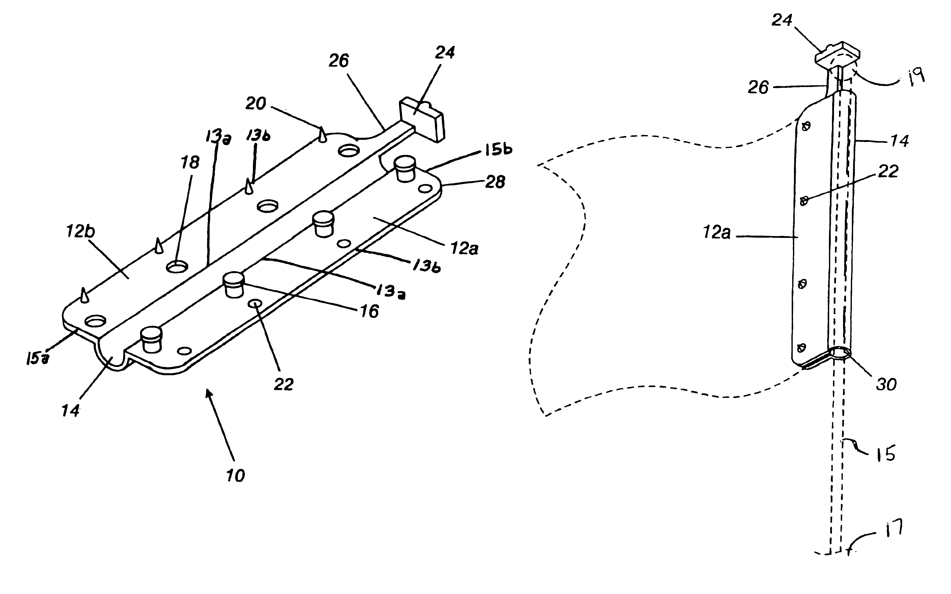
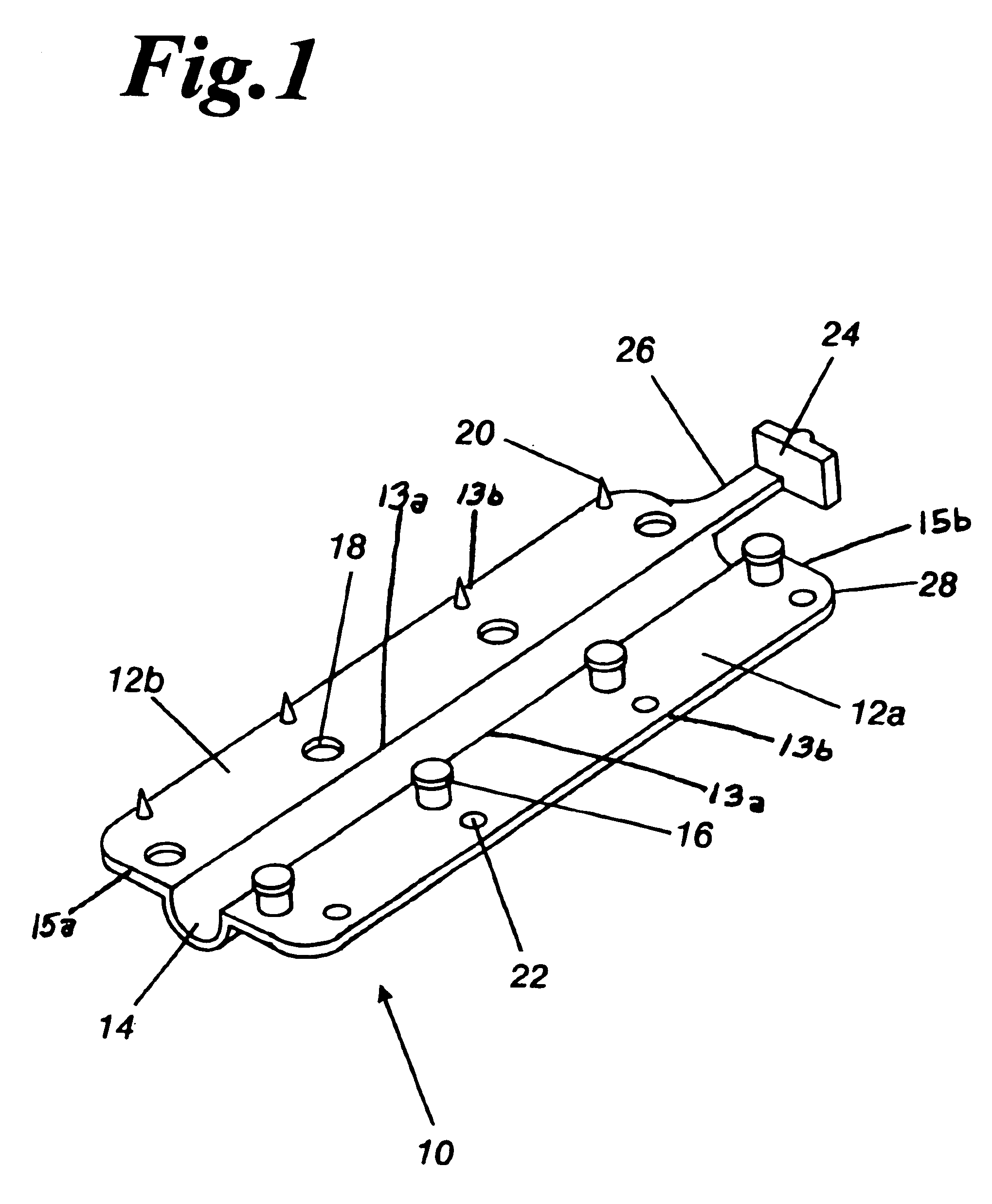
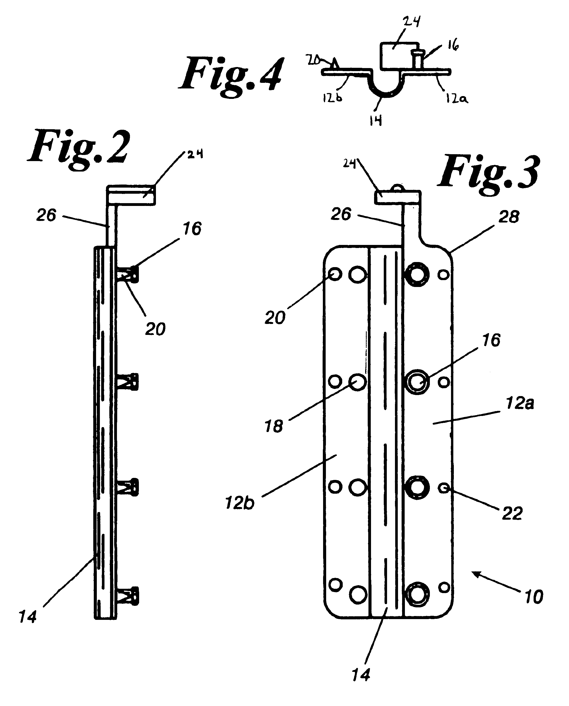
[0029]As required, detailed embodiments of the present invention are disclosed herein. However, it is to be understood by one of ordinary skill in the art that the present discussion is a description of exemplary embodiments only and is not intended as limiting the broader aspects of the present invention, which broader aspects are embodied in the exemplary construction.

[0030]The present invention is preferably unitary in construction and is useful with any plastic or other elastomeric material or any combination thereof. By unitary, it is meant that the present invention is formed as one continuous apparatus as opposed to separate parts which are joined to form one apparatus. Suitable plastics are recycled plastics, injection molded plastics, reinforced plastics or the like generally comprised of polyethylene, polypropylene, and polyvinylchloride. Further, the described configuration can be in different sizes and shapes to correspond to different designs and characteristics of auto...


PUM


Abstract

The present invention is directed to a garment clamping device for automobile antennas upon which a flag or banner may be secured and displayed. The clamping device comprises two generally rectangular shaped halves which are joined together by a hinge strap mechanism. Each half has at least one aperture and at least one corresponding mounting stud for clamping the two halves around an automobile antenna. Further, each half has at least one barb and at least one corresponding aperture located on the other half for holding and supporting a display flag after the apparatus is clamped around the antenna. Extending from one half is a cap for securing the apparatus atop the antenna. In operation, the device is positioned around an antenna and the mounting stud, barbs and respective apertures are engaged. Once engaged, the hinge straps form a cavity wherein the antenna is displaced. The cap of the device is positioned so that it rests upon the antenna ball located atop the antenna thereby keeping the clamp in a visibly appealing position. In certain embodiments, additional support is provided by a tape strip or other adhesive. In certain other embodiments, an attachment means for attaching the device to a bicycle or motor bike is provided. The attachment means comprises an elongated shaft and a second clamping device.

Description

CROSS REFERENCE TO RELATED APPLICATION[0001]This is a Continuation-In-Part Application of U.S. patent application Ser. No. 29 / 132,238 filed Nov. 6, 2000 now U.S. Pat. No. D448,702.FIELD OF THE INVENTION[0002]The present invention relates to an apparatus for supporting flags and banners on automobile antennas, and more particularly pertains to an apparatus which supports and removably displays flags or banners at the top of automobile antennas.BACKGROUND OF THE INVENTION[0003]Often it is desirable for an individual to display a symbol or word(s) from an automobile. These displays take many forms and are used for many purposes, including but not limited too advertising athletic teams, professional organizations, political groups, etc. Some individuals place bumper stickers on their automobiles, others place flags or banners on their car and some prefer to place signs on the sides or hood of the car. Each of the currently known methods and devices have certain disadvantages. By way of ...

Claims


Application Information

Patent Timeline
Patent Type & Authority Patents(United States)
IPC IPC(8): H01Q1/12H01Q1/32H01Q1/44F16B5/06
CPCH01Q1/1228H01Q1/325H01Q1/44F16B5/0692Y10T403/4966Y10T16/52Y10T403/4974
Inventor HAWKINS, MARK W
Owner HAWKINS MARK W
Why Eureka
Try Eureka