Non-vibrating ball check valve

a ball check valve and non-vibration technology, applied in the field of check valves, can solve the problems of ball check valves tripping, rattling stems, ball tripping within the valve housing,

Inactive Publication Date: 2005-05-31
SPEARS MFG
View PDF13 Cites 26 Cited by
  • Summary
  • Abstract
  • Description
  • Claims
  • Application Information

AI Technical Summary

Problems solved by technology

A problem, however, arises in the use of ball check valves regarding the fact that ball check valves have a tendency to rattle, as illustrated in FIG. 1.
Such rattling stems from turbulence within the liquid flowing through the valve.
Such turbulence causes the ball to rattle within the valve housing.
Such reduction in the clearance between the ball and the body of the valve causes additional friction between the fluid, the valve ball and the valve body.
Such friction tends to drag the ball downstream and hold it firmly against the downstream end of the valve body.
Although this method is relatively effective in minimizing rattle, it suffers from the disadvantage that the additional friction dissipates the kinetic energy of the flowing liquid, thereby increasing pressure drop across the valve.
Unfortunately, this second method also results in a decrease in the kinetic energy of the liquid flowing through the valve and therefore also increases the pressure drop across the valve.

Method used


Image

  • Non-vibrating ball check valve
  • Non-vibrating ball check valve
  • Non-vibrating ball check valve

Examples


example

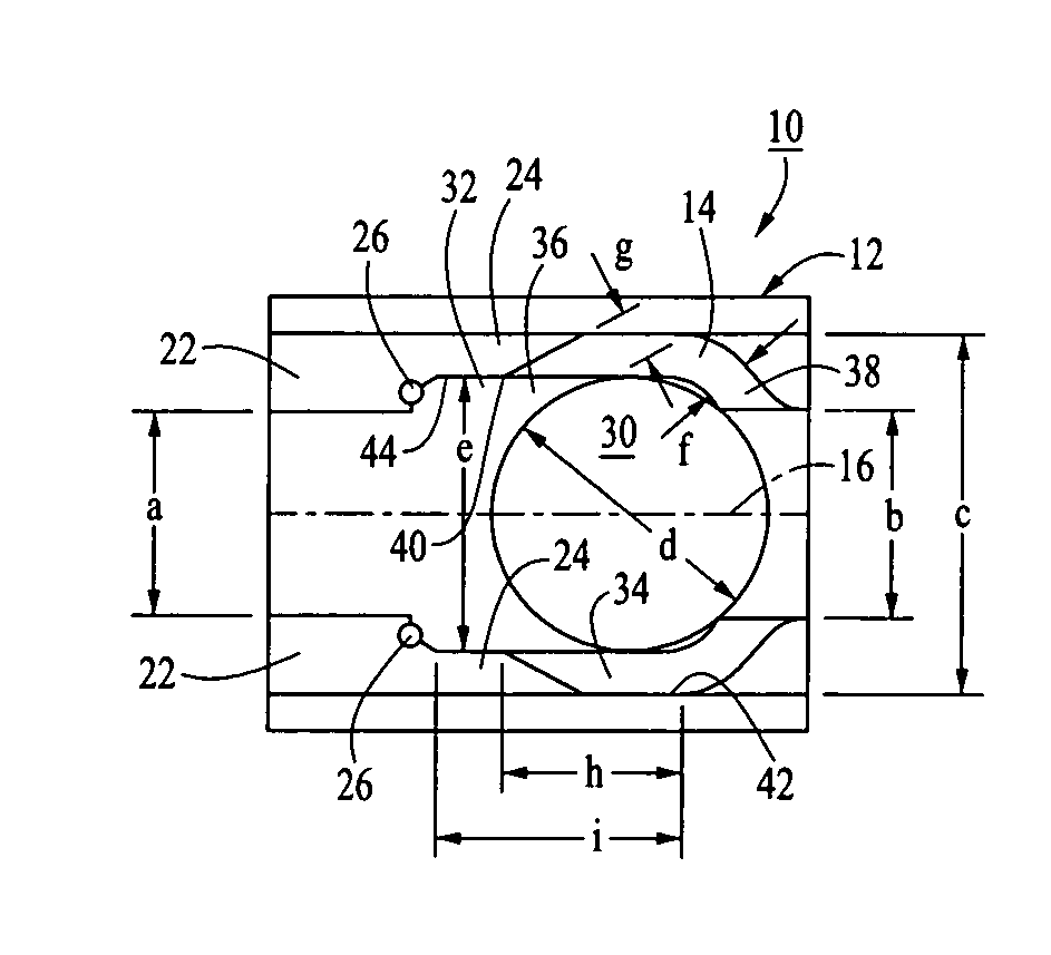
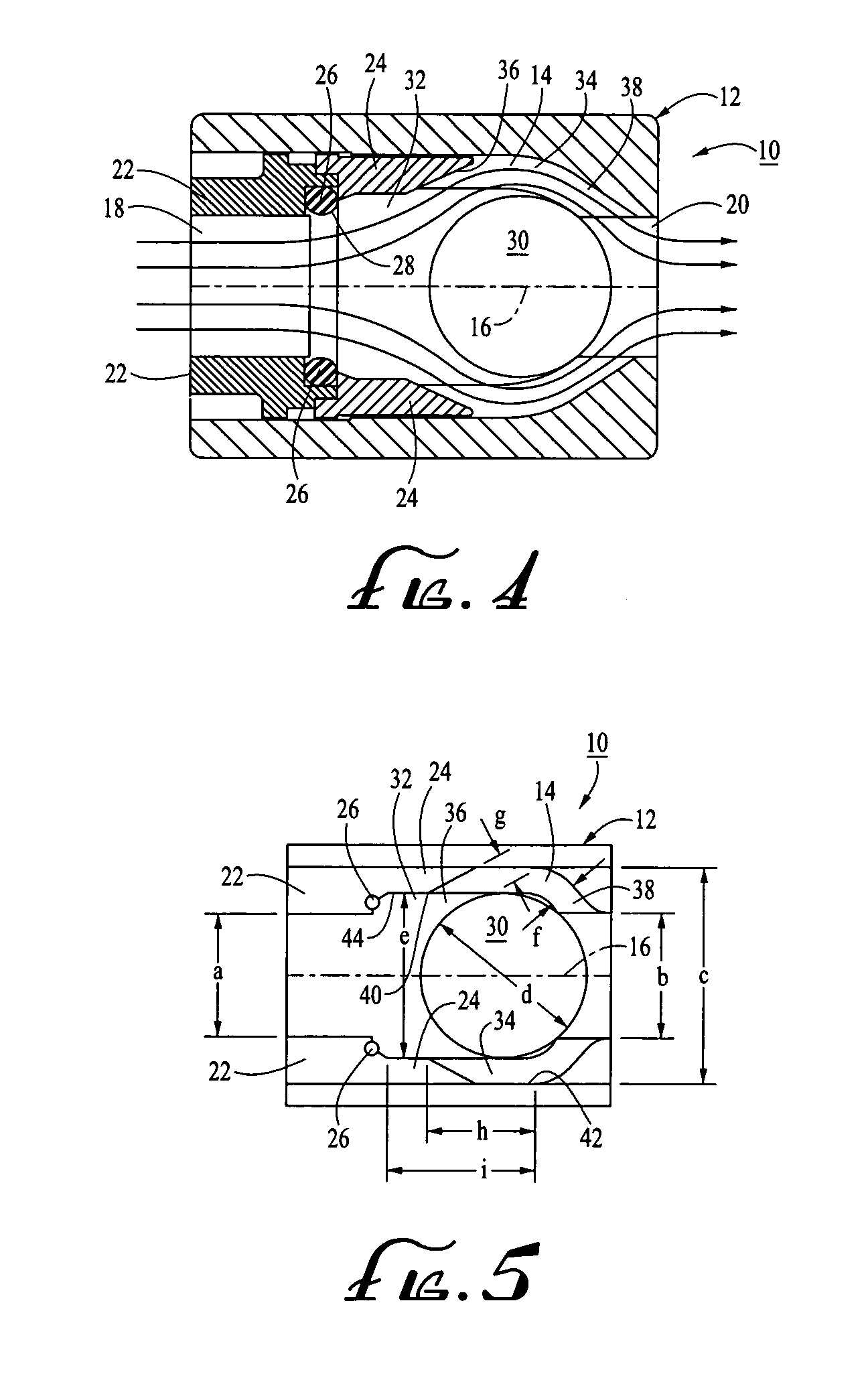
[0027]In a typical example of the invention, the interior diameter a of the inlet port 18 and the interior diameter b of the outlet port 20 are 1.5 inches. The bore section 34 of the valve body chamber 14 has a diameter c of 2.5 inches. The valve ball 30 has a diameter d of 1.89 inches. The valve body chamber 14 has a body clearance section 32 with a diameter e of 1.89 inches. The clearance f between the valve ball 30 and the downstream transition section 38 when the valve ball 30 is disposed in the downstream-most position is a distance of 0.27 inches. The clearance g between the valve ball 30 and the upstream transition section 36 when the valve ball 30 is in the downstream-most position is also 0.27 inches. The distance h along the longitudinal axis 16 of the valve body chamber 14 between the downstream end 40 of the body clearance section 32 and the downstream end 42 of the bore section 34 is 0.859 inches. The distance i along the longitudinal axis 16 of the valve chamber 14 bet...


PUM


Abstract

A ball check valve comprises a valve body chamber which includes an inlet opening, an outlet opening, and a ball that is free to travel within the valve body chamber. A valve seat is adapted for receiving the ball. A body clearance section is located downstream of the inlet opening. A bore section is located downstream of the body clearance section. Fluid flow is allowed to flow through the valve body from the inlet opening through the outlet opening, but fluid flow through the valve body from the outlet opening through the inlet opening is prohibited by the interaction of the ball and the valve seat. The inlet opening is smoothly contoured to urge fluid flow between the inlet opening and the outlet opening to be laminar in nature.

Description

RELATED APPLICATION[0001]This invention is a continuation of U.S. Provisional Patent Application Ser. No. 60 / 311,109, filed Aug. 9, 2001 entitled “Non-Vibrating Ball Check Valve,” the entirety of which is incorporated herein by this reference.FIELD OF THE INVENTION[0002]This invention relates generally to check valves and, more specifically, to ball check valves.BACKGROUND OF THE INVENTION[0003]Ball check valves are very popular types of check valves for use in liquid flow lines. The popularity of ball check valves stems from their relative simplicity of design and their relative inexpense of manufacture.[0004]A problem, however, arises in the use of ball check valves regarding the fact that ball check valves have a tendency to rattle, as illustrated in FIG. 1. Such rattling stems from turbulence within the liquid flowing through the valve. Such turbulence causes the ball to rattle within the valve housing.[0005]Several attempts have been made to minimize rattling within ball check ...

Claims


Application Information

Patent Timeline
Patent Type & Authority Patents(United States)
IPC IPC(8): F16K15/04F16K15/02
CPCF16K15/04Y10T137/7912Y10T137/791
Inventor SWINGLEY, DOUGLAS
Owner SPEARS MFG
Why Eureka
Try Eureka