Balanced flow cooling

a technology of balanced flow and cooling, applied in the field of modular electronic circuits, can solve the problems of increasing the number and complexity of components mounted on the front and rear faces of the modules, leaving little room for ventilation fans or ventilation openings

Inactive Publication Date: 2005-05-31
ORACLE INT CORP
View PDF13 Cites 46 Cited by
  • Summary
  • Abstract
  • Description
  • Claims
  • Application Information

AI Technical Summary

Benefits of technology

[0010]A yet further aspect of the invention provides for a “dummy” module to replace an electronics module in a rack while the electronics module is removed for servicing, the dummy module having mounting elements to cooperate with the rack, and ducts to provide a sealed connection between the air inlet and / or outlet openings of the electronics modules adjacent the removed module. Cooling air supply to the remaining modules is preserved by the presence of the dummy module, whose ducts replace the membranes of the removed module, so that the remaining electronics modules may continue to operate without overheating.

Problems solved by technology

This increasing number and complexity of components mounted on the front and rear faces of the module leaves little room for ventilation fans or ventilation openings.

Method used


Image

  • Balanced flow cooling
  • Balanced flow cooling
  • Balanced flow cooling

Examples


Embodiment Construction

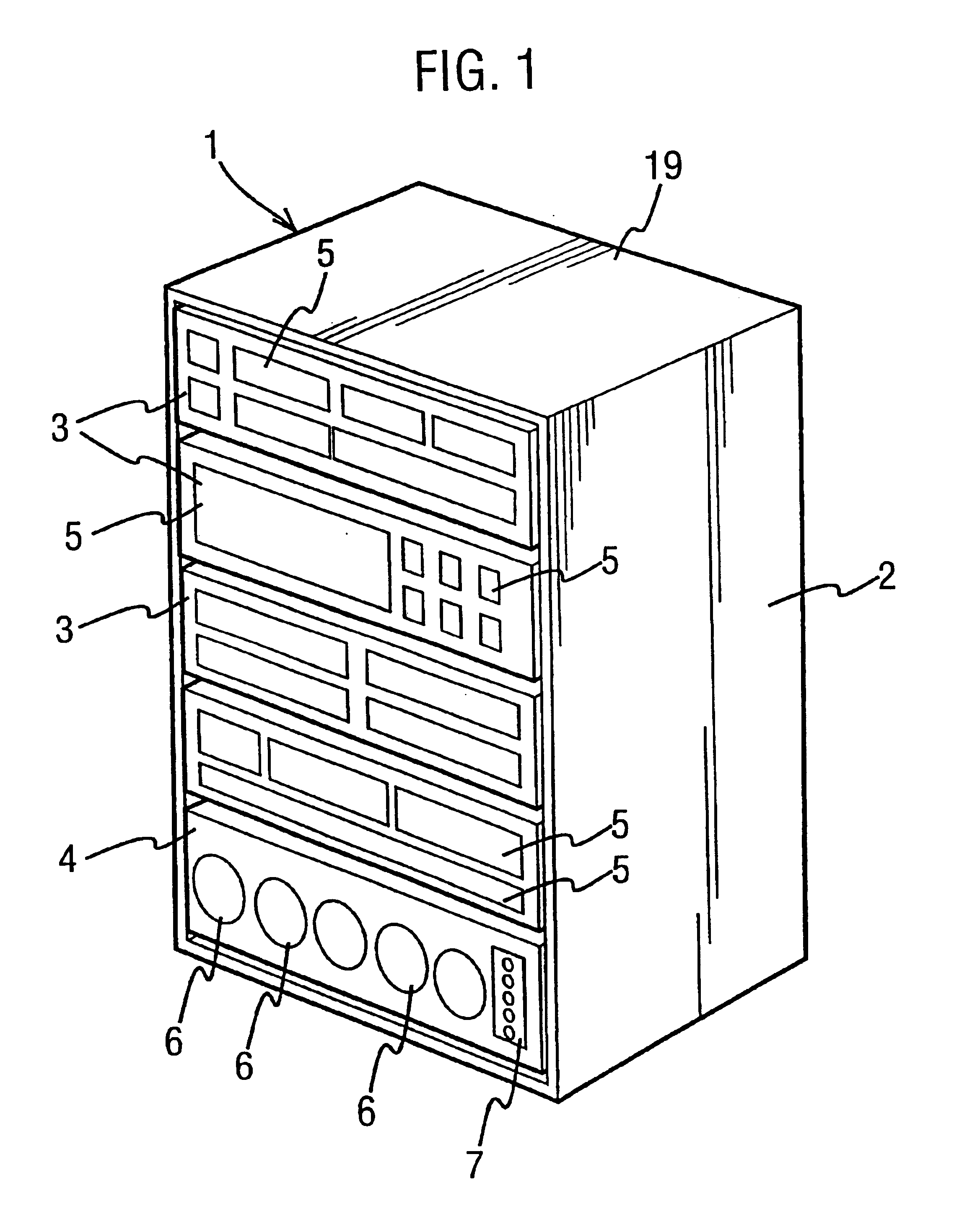
[0019]Referring now to the drawings, in which like parts will be given like reference numerals, FIG. 1 shows a modular assembly 1 comprising a supporting structure or rack 2, a plurality of circuit modules 3 mounted in a vertically-extending array in the rack 2, and a ventilation module 4 mounted below the array of circuit modules 3. The front faces of the circuit modules 3 are visible in FIG. 1, and components 5 of the electronic circuits contained within the circuit modules 3 are mounted to the front faces of the modules. The components 5 may be switches, indicator devices, media drives, or other components to which access is required during operation or maintenance of the circuits contained in the modular assembly.

[0020]The ventilation module 4 has mounted to its front face a number of fans 6 and an indicator panel 7. The indicator panel 7 may comprise indicator lights to show the operational states of the fans 6 of the ventilation module 4.

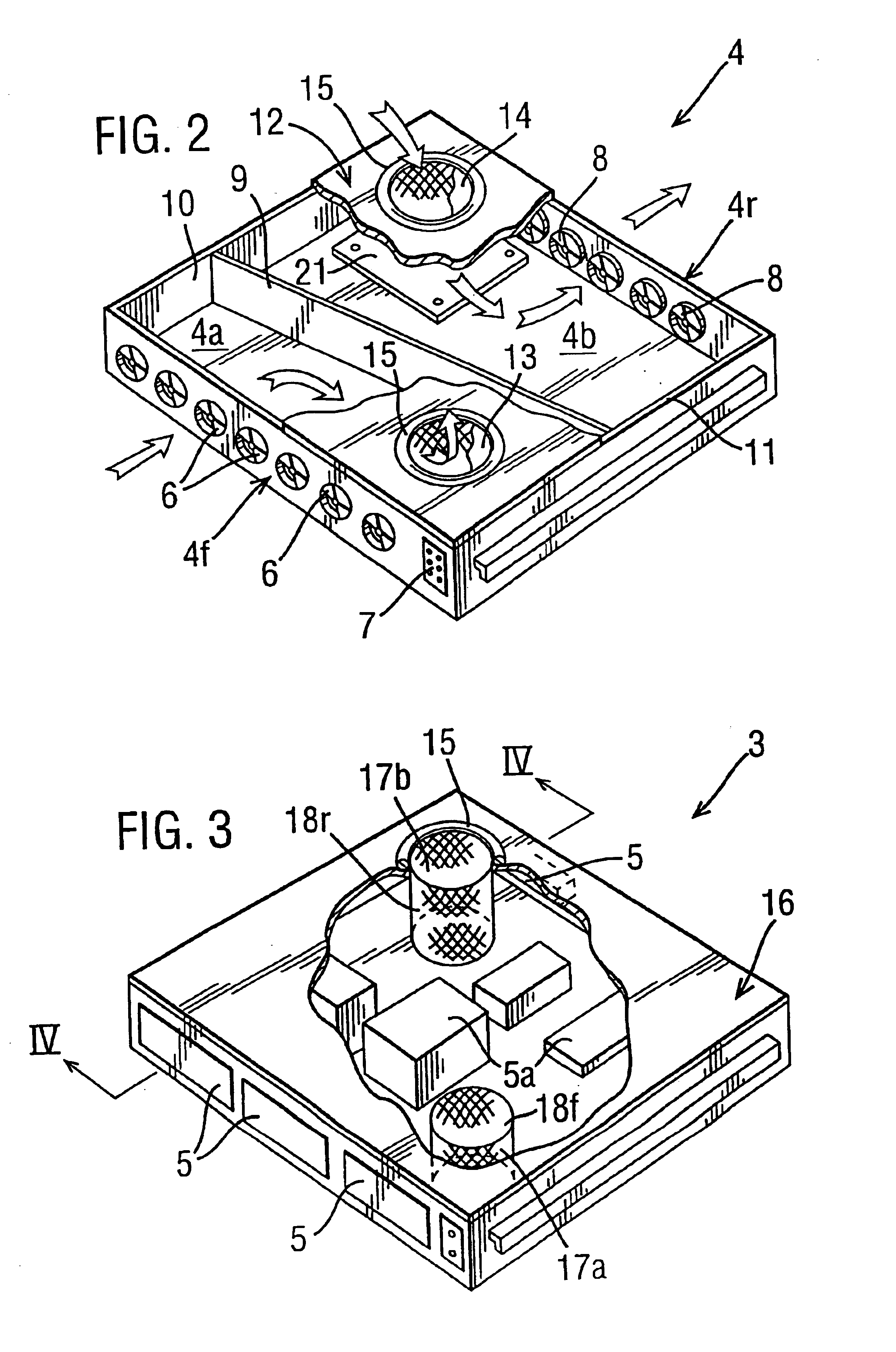
[0021]FIG. 2 is a perspective view of t...


PUM


Abstract

There is described a modular electronic circuit wherein a series of electronics modules are penetrated by a passageway having an air-permeable wall, and cooling air is supplied to the passageway at a pressure above that obtaining in the modules, so that each module receives a supply of air passing out through the wall of the passageway. The passageway is constituted by a plurality of aligned tubular sleeves mounted in respective modules. There is also described a ventilation module including blowers to pressurize the passageway. A second passageway may be provided, at a reduced pressure, to extract air from the modules.

Description

FIELD OF INVENTION[0001]The present invention relates to modular electronic circuits, and is particularly concerned with the provision of cooling air flows through electronic circuit modules.BACKGROUND OF THE INVENTION[0002]Complex electronic circuits are frequently implemented by assembling a plurality of individually cased circuit modules in a supporting rack, with electrical interconnection between the modules being effected by cabling.[0003]The electronic components within each module require cooling, and to provide such an airflow cooling fans are often installed on the front and / or back faces of each module so that air is drawn into the module through openings in the front face and is expelled through openings in the rear face.[0004]When the modules are assembled into a rack, only the front and rear faces are accessible. As the circuit modules become more complex, the rear face of the module is increasingly taken up by the provision of connectors for linking the modules togeth...

Claims


Application Information

Patent Timeline
Patent Type & Authority Patents(United States)
IPC IPC(8): H05K7/20
CPCH05K7/20736H05K7/20727
Inventor GRAVELL, ANTHONY R.BARLOW, RICHARD J.
Owner ORACLE INT CORP
Why Eureka
Try Eureka