PWM power converter controlled by transistion detection of a comparator error signal

a technology of comparator error and power converter, which is applied in the direction of electric variable regulation, process and machine control, instruments, etc., can solve the problems of reducing the cost and complexity increasing the complexity and cost of the control system, and introducing difficulties in regulation accuracy

Inactive Publication Date: 2005-05-31
HERCULES TECH GROWTH CAPITAL
View PDF47 Cites 99 Cited by
  • Summary
  • Abstract
  • Description
  • Claims
  • Application Information

AI Technical Summary

Problems solved by technology

Obtaining the output voltage feedback signal from the secondary side of the converter, as shown in FIG. 1, offers the potential of accurate regulation performance, but necessarily increases the complexity and cost of the control system.
If a primary-side feedback system were used instead, the output voltage feedback signal would be obtained from the primary side of power transformer T1, reducing cost and complexity of the control system, but introducing difficulties with regulation accuracy.
Hence, measuring the output voltage Vout through the reflected flyback voltage is problematic, as parasitic losses act as a corrupting signal that cannot be removed by filtering.
As such, prior art primary-side feedback systems, such as that disclosed in U.S. Pat. No. 5,438,499, which depends upon the reflected voltage, are challenged to provide good voltage regulation.

Method used


Image

  • PWM power converter controlled by transistion detection of a comparator error signal
  • PWM power converter controlled by transistion detection of a comparator error signal
  • PWM power converter controlled by transistion detection of a comparator error signal

Examples


Embodiment Construction

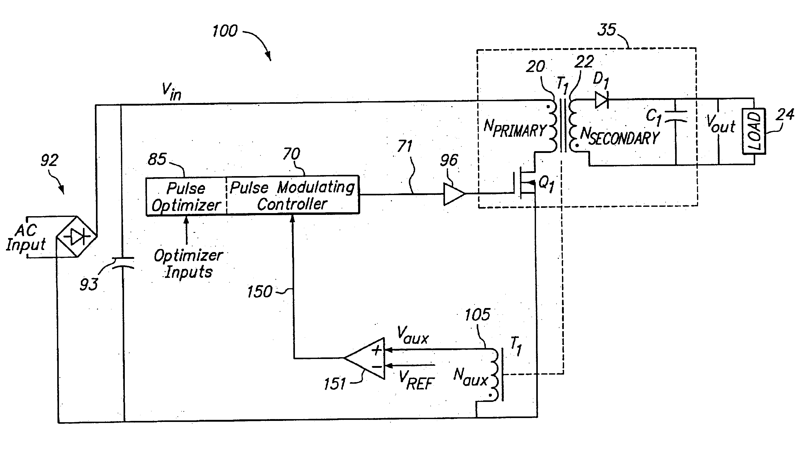
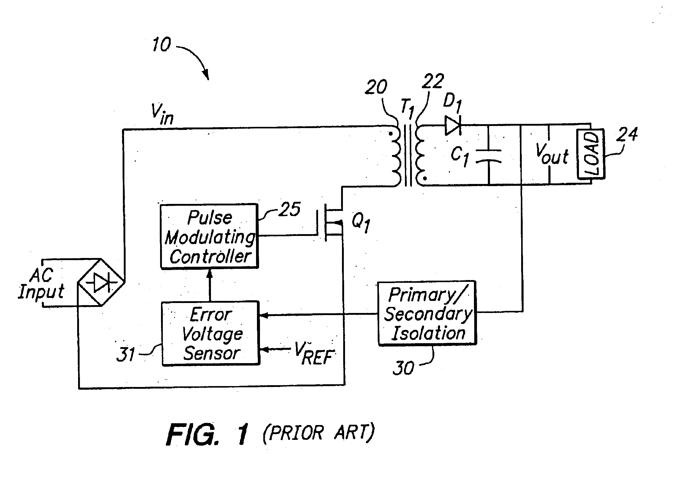
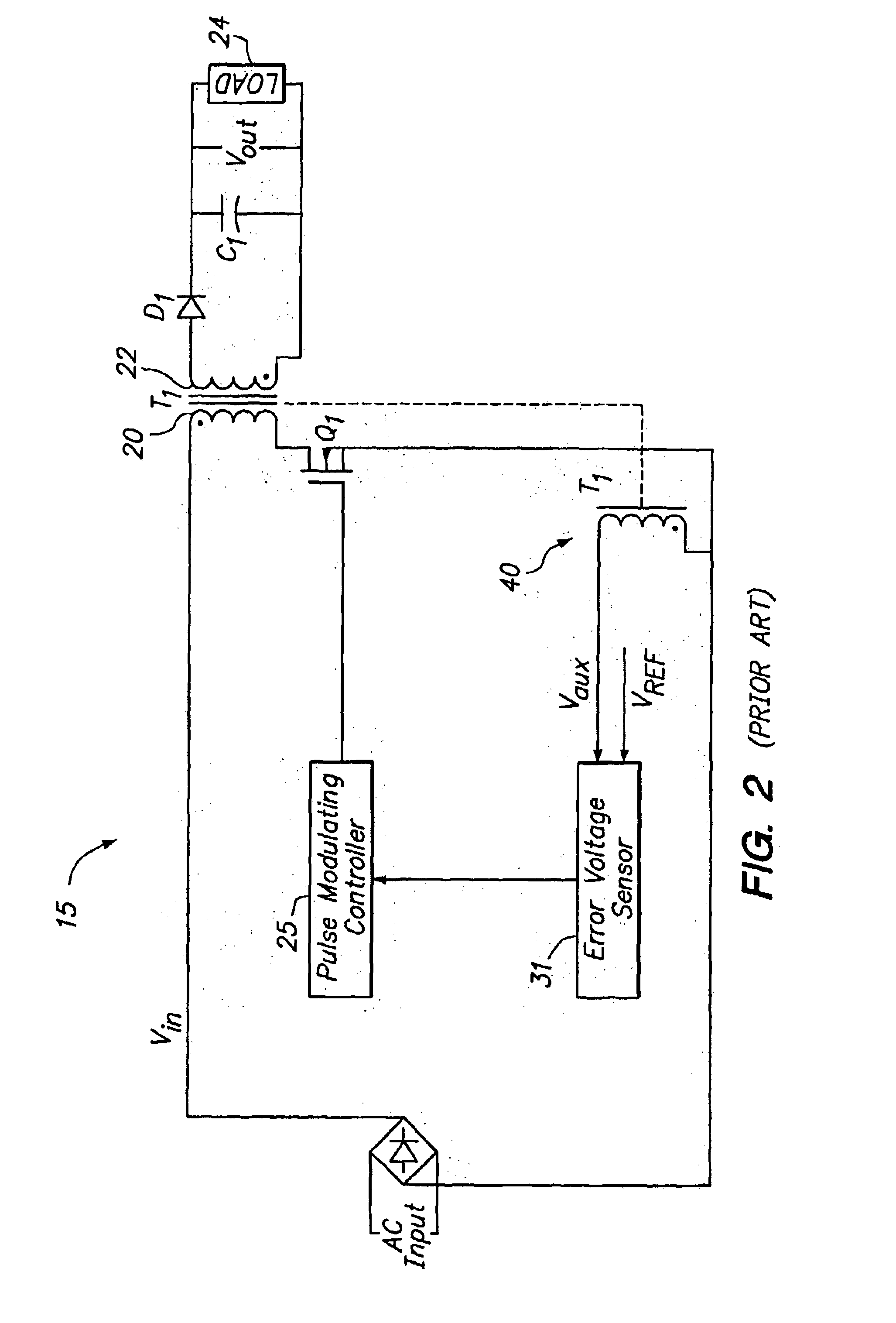
[0034]It will be apparent to those skilled in the art that the power converter control system methodologies and embodiments disclosed and described herein may be applied to transformer-coupled switching converters, such as a flyback, forward, fly-forward, push-pull, or bridge-type power converters. In addition, as will be explained herein, direct-coupled switching power converters such as buck, boost, buck / boost or SEPIC power converters may also benefit from these control methodologies and embodiments.

[0035]The above-incorporated U.S. Pat. No. 6,275,018 discloses and describes various embodiments of a “pulse rate” (also referred to as “pulse train”) method of power converter regulation. Notably, pulse rate regulation, in itself, controls neither the ON TIME nor the OFF TIME of the power switch in order to regulate the output voltage. Instead, output regulation may be accomplished by controlling the rate of independently specified activation pulses presented to the power switch. If ...


PUM


Abstract

A method of regulating voltage at an output of a switching power converter includes sensing an output voltage feedback signal; comparing the sensed feedback signal to a reference at a determined time during a cycling of the switch; and regulating the output voltage by either enabling or inhibiting cycling of a switch by a cycle of a drive signal produced by pulse generation circuitry in response to an output of the comparison.

Description

RELATED APPLICATION DATA[0001]This application claims priority to provisional application Ser. No. 60 / 335,723, filed Nov. 29, 2001, which is fully incorporated herein by reference.FIELD OF INVENTION[0002]The invention pertains generally to the field of power conversion and more particularly to methods of controlling power converters.BACKGROUND[0003]Switching power converters offer both compactness and efficiency in a number of different topologies that can be placed in two main categories: isolated (or transformer-coupled) and non-isolated (or direct-coupled). In non-isolated switching power converters, such as a buck (reducing voltage) or boost (increasing voltage) converter, the power output is directly coupled to the power input through the power switch element. In contrast, in isolated power converters, such as flyback or forward converters, the power output is isolated from the power input through a transformer, with the power switch element located on the primary (input) side ...

Claims


Application Information

Patent Timeline
Patent Type & Authority Patents(United States)
IPC IPC(8): H02M3/157H02M3/04H02M3/156H02M3/335H02M3/24
CPCH02M3/156H02M3/157H02M3/33523H02M3/33515H02M2001/0041H02M1/0041
Inventor MUEGGE, MARK R.EASON, MARKTELEFUS, MARK D.
Owner HERCULES TECH GROWTH CAPITAL
Why Eureka
Try Eureka