
Systems and methods for constant voltage mode and constant current mode in flyback power converters with primary-side sensing and regulation

a technology of constant current and flyback power converter, which is applied in the direction of electric variable regulation, process and machine control, instruments, etc., can solve the problems of increasing system cost, difficulty in compensating voltage drop due to cable loss, and control scheme as described above often has poor output voltage regulation, so as to reduce system cost, improve reliability and/or efficiency, the effect of reducing the number of parts

Active Publication Date: 2012-03-29
ON BRIGHT ELECTRONICS SHANGHAI
View PDF4 Cites 184 Cited by
  • Summary
  • Abstract
  • Description
  • Claims
  • Application Information

AI Technical Summary

Benefits of technology

The present invention provides systems and methods for regulating power converters. The invention includes a sampling component, an error amplifier, a feed forward component, a compensation component, and a controller for regulating output current and voltage. The invention also includes an oscillator and a second signal generator for generating a clock signal and a second control signal. The technical effects of the invention include improved regulation of power converters and improved efficiency in power conversion.

Problems solved by technology

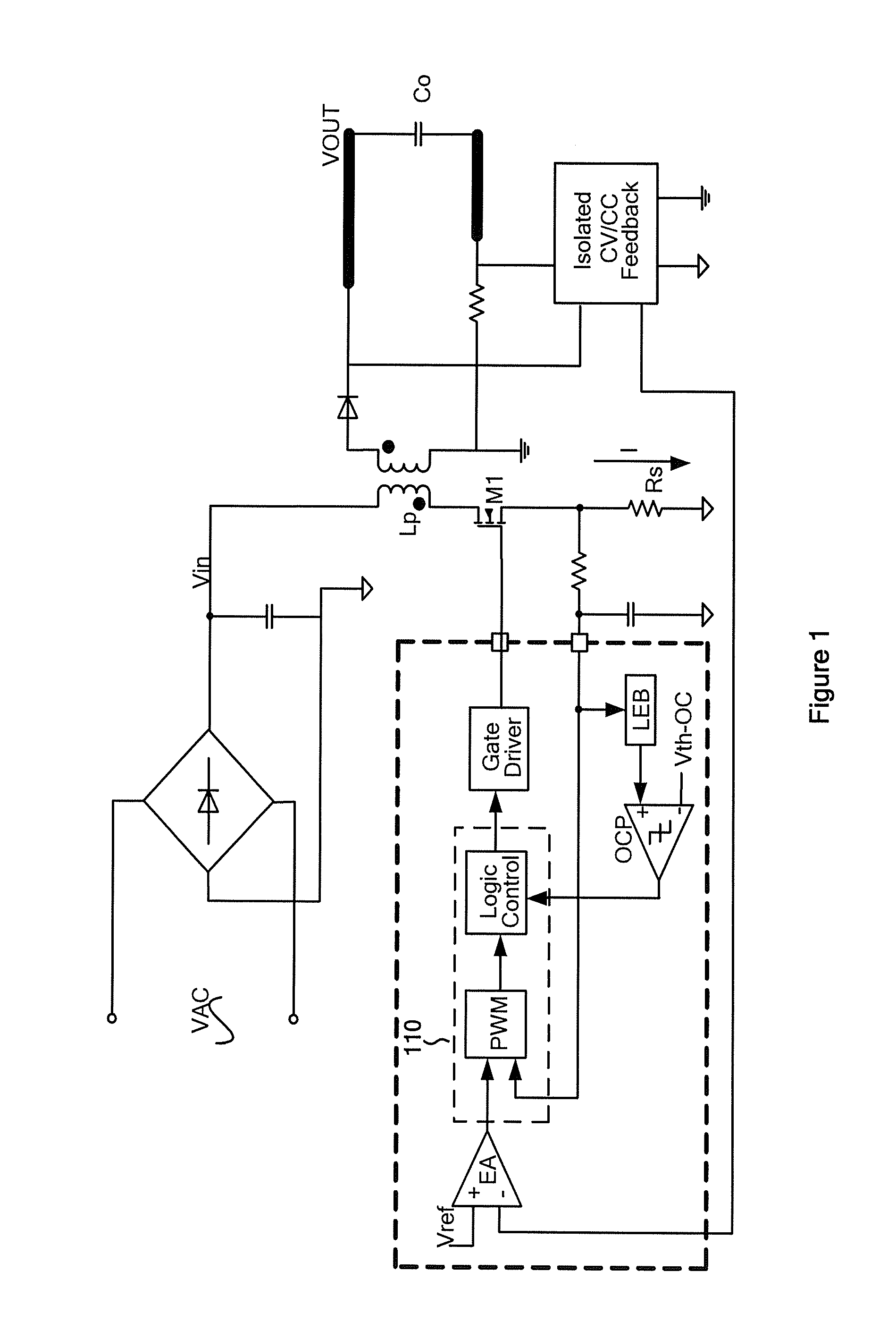
In addition to increasing the system cost, the voltage drop due to the cable loss usually is difficult to compensate.
Additionally, the control scheme as described above often has poor regulation for output voltage due to the change in the forward voltage of the diode D2.
According to some conventional technology, the output current may depend on the inductance of the primary winding; therefore the output current often suffers from large variations, which usually cannot be effectively compensated in mass production.

Method used


Image

  • Systems and methods for constant voltage mode and constant current mode in flyback power converters with primary-side sensing and regulation
  • Systems and methods for constant voltage mode and constant current mode in flyback power converters with primary-side sensing and regulation
  • Systems and methods for constant voltage mode and constant current mode in flyback power converters with primary-side sensing and regulation

Examples


Embodiment Construction

[0102]The present invention is directed to integrated circuits. More particularly, the invention provides systems and methods for constant voltage mode and constant current mode. Merely by way of example, the invention has been applied to a flyback power converter with primary-side sensing and regulation. But it would be recognized that the invention has a much broader range of applicability.

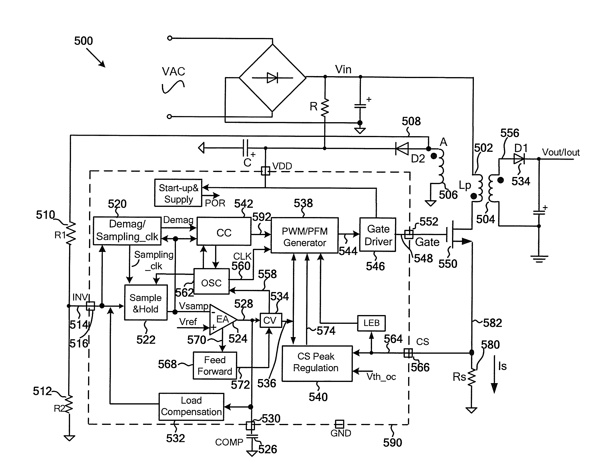
[0103]FIG. 7 is a simplified diagram for a switch-mode power conversion system with primary-side sensing and regulation according to an embodiment of the present invention. This diagram is merely an example, which should not unduly limit the scope of the claims. One of ordinary skill in the art would recognize many variations, alternatives, and modifications.

[0104]A switch-mode power conversion system 500 includes a primary winding 502, a secondary winding 504, and an auxiliary winding 506. Additionally, the conversion system 500 includes resistors 510, 512, and 580. Moreover, the conversion sys...


PUM


Abstract

System and method for regulating a power converter. The system includes a first signal generator configured to receive a first sensed signal and generate an output signal associated with demagnetization. The first sensed signal is related to a first winding coupled to a secondary winding for a power converter, and the secondary winding is associated with at least an output current for the power converter. Additionally, the system includes a ramping signal generator configured to receive the output signal and generate a ramping signal, and a first comparator configured to receive the ramping signal and a first threshold signal and generate a first comparison signal based on at least information associated with the ramping signal and the first threshold signal. Moreover, the system includes a second comparator configured to receive a second sensed signal and a second threshold signal and generate a second comparison signal.

Description

1. CROSS-REFERENCES TO RELATED APPLICATIONS[0001]This application claims priority to Chinese Patent Application No. 201110051423.2, filed Feb. 28, 2011, commonly assigned, incorporated by reference herein for all purposes. Additionally, this application is a continuation-in-part of U.S. patent application Ser. No. 12 / 581,775, filed Oct. 19, 2009, which claims priority to U.S. Provisional No. 61 / 107,249, filed Oct. 21, 2008, both applications commonly assigned and incorporated by reference herein for all purposes.[0002]Additionally, this application is related to U.S. patent application Ser. No. 12 / 502,866, commonly assigned, incorporated by reference herein for all purposes.2. BACKGROUND OF THE INVENTION[0003]The present invention is directed to integrated circuits. More particularly, the invention provides systems and methods for constant voltage mode and constant current mode. Merely by way of example, the invention has been applied to a flyback power converter with primary-side s...

Claims


Application Information

Patent Timeline
Patent Type & Authority Applications(United States)
IPC IPC(8): H02M3/335H05B44/00
CPCH02M3/335H02M3/33523H05B45/385H02M1/0009H02M1/08H02M3/33515
Inventor ZHANG, YUNCHAOCAO, YAMINGHUANG, XIAOMINZHANG, XIUHONGFANG, LIEYI
Owner ON BRIGHT ELECTRONICS SHANGHAI
Learn More