Switching regulator with advanced slope compensation

a technology of slope compensation and switching regulator, which is applied in the direction of power conversion systems, instruments, dc-dc conversion, etc., can solve the problems of inability to achieve the true maximum current that can pass through the switch b>108/b>, and inability to achieve stable current. the effect of 108

Inactive Publication Date: 2006-01-12
COLLABO INNOVATIONS INC
View PDF20 Cites 25 Cited by
  • Summary
  • Abstract
  • Description
  • Claims
  • Application Information

AI Technical Summary

Benefits of technology

[0015] This disclosure presents improved switching regulators having simplified circuit design that provides slope compensation without changing the maximum current passing through a switch that controls the supply of power from a power source to a load.

Problems solved by technology

In current-mode switching voltage regulators, i.e., a switching regulator that is controlled by a current-derived signal in the regulator, there is an inherent instability when the duty cycle exceeds 50% with fixed frequency and continuous current mode, and 67% with fixed frequency and discontinuous current mode (i.e., when the switch is ON for more than 50% or 67% of a given switching period).
However, as mentioned above, current-mode voltage regulators can become unstable when the duty cycle exceeds 50% with fixed frequency and continuous current mode.
One undesirable consequence of slope compensation is that the true maximum current that can pass through switch 108 decreases proportionally as the duty cycle increases.
Merely increasing the clamp voltage directly (e.g., by increasing the value of voltage source 120 with a signal varying at the compensation ramp rate) is not a viable solution because the large time constant of capacitor 127 will not allow the peak value of VC to respond to a changing clamp threshold fast enough.
Moreover, simply adding the compensation voltage directly to VC nulls the effect of slope compensation.
However, the additional components, such as the buffer circuit 140 and the adjustable voltage clamp circuit 150, that are needed to implement an adjustable limiter voltage as shown in FIG. 2 increase cost and design complexity.
Furthermore, the use of two compensation currents, ISC1 and ISC2 in the circuit shown in FIG. 2 also add design complexity.
The additional circuits needed in the circuit 210 shown in FIG. 2 also increase the die size of the part, which is undesirable in integrated circuit or semiconductor component designs.
Moreover, the use of additional components, especially active components such as amplifiers, would increase consumption of power.

Method used


Image

  • Switching regulator with advanced slope compensation
  • Switching regulator with advanced slope compensation
  • Switching regulator with advanced slope compensation

Examples


Embodiment Construction

[0027] In the following description, for the purposes of explanation, numerous specific details are set forth in order to provide a thorough understanding of the present disclosure. It will be apparent, however, to one skilled in the art that the present method and system may be practiced without these specific details. In other instances, well-known structures and devices are shown in block diagram form in order to avoid unnecessarily obscuring the present disclosure.

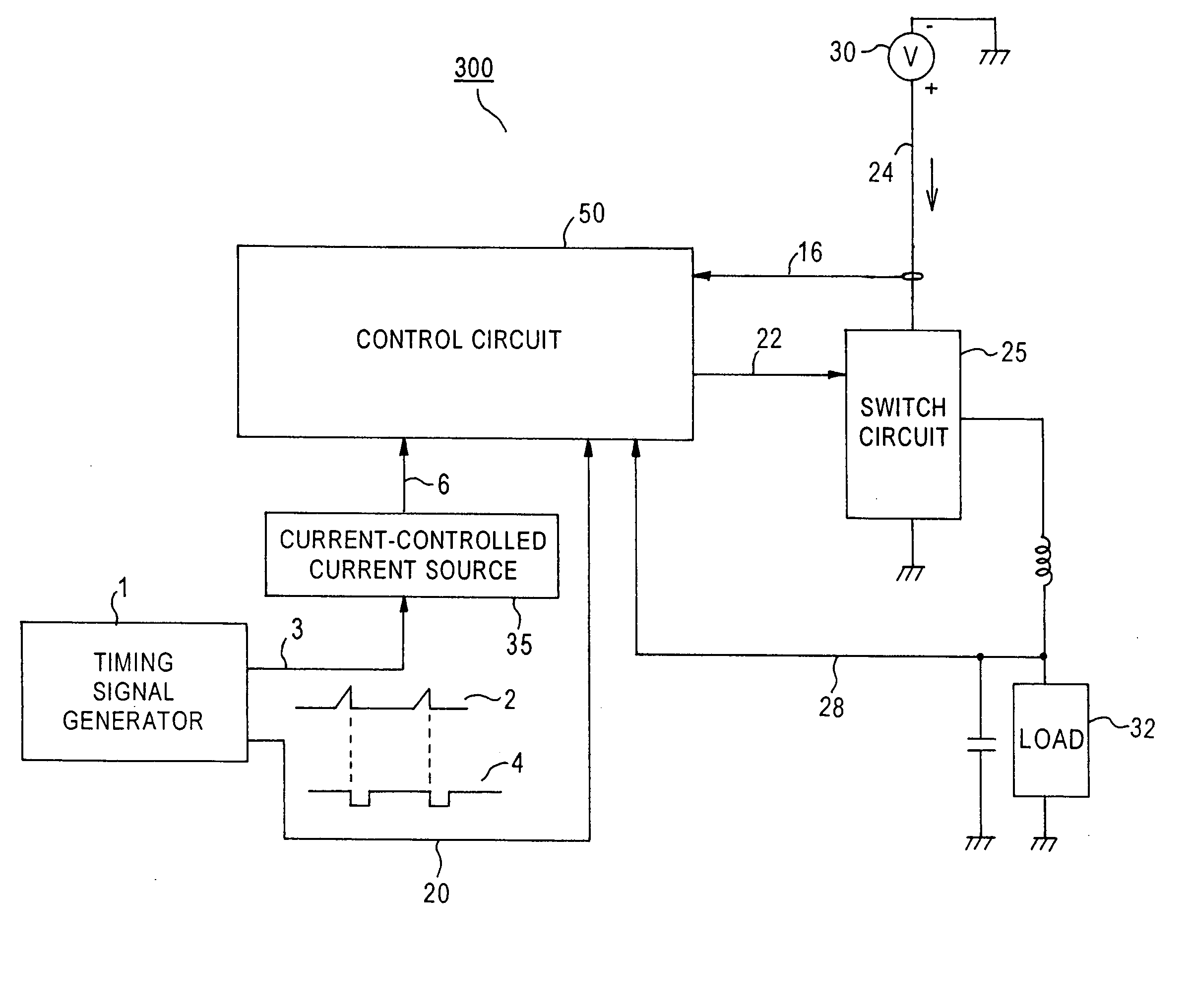
[0028]FIG. 3 depicts an exemplary block diagram of an exemplary switching regulator 300 with improved slope compensation according to this disclosure. Switching regulator 300 provides a predetermined and substantially constant output voltage to a load 32 from a voltage source 30. Switching regulator 300 includes a control circuit 50 that generates a control signal 22 to control the operation of a switch circuit 25, which in turn controls the coupling of load 32 to voltage source 30 or ground. Control signal 22 is slop...


PUM


Abstract

A switching regulator circuit with improved slope compensation for providing a regulated voltage to a load. The regulator circuit includes a power source and a switch circuit configured to control the coupling of the power source to the load. The operation of the switch circuit is controlled by a control signal generated by a control circuit. A feedback circuit is provided for generating a feedback signal indicative of the regulated voltage provided by the switching regulator circuit to the load. A circuit is provided to generate a sensed signal indicative of the current supplied by the power source. The regulator circuit further includes a timing signal generator for generating a timing signal, a ramp signal generator for generating a ramp signal, and a current source controlled by the ramp signal for generating a compensation signal indicative of the ramp signal. The control circuit generates the control signal based on the compensation signal, the timing signal, the sensed signal and the feedback signal.

Description

FIELD OF DISCLOSURE [0001] This disclosure generally relates to improved switching regulator circuits, and more specifically, to methods and circuits to effectively implement slope compensation in switching regulator circuits with reduced cost and design complexity. BACKGROUND OF THE DISCLOSURE [0002] A voltage regulator provides a predetermined and substantially constant output voltage to a load from a voltage source that may be poorly-specified or fluctuating. One type of commonly used regulator is a switching regulator, which supplies a flow of current from a voltage source to a load in the form of discrete current pulses. To create the discrete current pulses, switching regulators usually employ a switch, such as a power transistor, to control the current supply. The current pulses are then converted into a steady load current with an inductive storage element. By controlling the duty cycle of this switch, i.e., the percentage of time that the switch is ON relative to the total ...

Claims


Application Information

Patent Timeline
Patent Type & Authority Applications(United States)
IPC IPC(8): G05F1/40
CPCH02M3/156
Inventor OSWALD, RICHARD K.YAMAMOTO, TAMOTSU
Owner COLLABO INNOVATIONS INC
Why Eureka
Try Eureka