Method and apparatus of driving LED and OLED devices

a technology of led and oled devices, which is applied in the direction of electric variable regulation, process and machine control, instruments, etc., can solve the problems of affecting the rapid growth of ssl applications, high device cost and especially the total lighting system solution, and a large part of the system cost, so as to reduce the voltage stress and improve efficiency.

Inactive Publication Date: 2012-07-24
SUNTEC ENTERPRISES
View PDF4 Cites 25 Cited by
  • Summary
  • Abstract
  • Description
  • Claims
  • Application Information

AI Technical Summary

Benefits of technology

[0010]This invention proposes a concept to drive LED and OLED devices with simplified power conversion process and simplified circuit design. The proposed concept eliminates the voltage to voltage or current to voltage conversion stage in the conventional process and uses a current mode conversion circuit to drive the LED devices directly. It simplifies the conventional two stage or three stage design of the LED drive system to a single stage circuit for most applications. The concept also provides high versatility to the LED drive system design such that system behavior can be modified by minimal change of circuit design to support different applications.
[0012]In one embodiment if the power switch works at a fixed frequency and constant current mode, the LED current profile and brightness can be held constant regardless of the input voltage change. The LED current can be adjusted with a control signal to provide dimming control in continuous operation mode. Alternatively, the total light output can also be adjusted by turning converter on and off periodically in burst mode and changing the on duty in each period. And further, the dimming control can combine the two modes together to offer wider dimming range.
[0014]In one embodiment the LED carries out the function of both light emitting and reverse voltage blocking. Such approach eliminates the power loss and saves the cost of the rectifier diode. In the case the reverse voltage is higher than the LED reverse blocking capability, a serial diode can be used to protect the LED. A capacitor can also be connected in parallel with the LED to smooth out the ripple current.
[0017]In one embodiment a lossless snubber is employed to suppress the voltage stress on the power switch. Due to the stored energy in the transformer leakage inductance, severe voltage spike could occur at the power switch turn off transition. The lossless snubber absorbs the leakage energy at turn off transition and feeds the energy back to the system when the power switch turns on.
[0018]In another embodiment a chopper circuit is used to drive the LED from a DC or rectifier AC voltage directly. When the forward voltage of the LED or LED string is close to the input voltage such approach can avoid the effect of the transformer leakage inductance and yield higher efficiency. A current mode control is employed for such application.

Problems solved by technology

Despite the technical advantages of the LED and OLED, high cost of the devices and especially the total lighting system solutions is the most critical factor that hinders the fast growth of the SSL applications.
Apart from the device itself, the drive circuitry that converts the input electrical power from a commonly available format to a format that provides suitable voltage and current to the device, consists a large part of the system cost.
In applications that the input power is from the mains AC power line of 110V or 220V, the cost of the drive circuitry would be more significant because of the complexity of the power conversion process that very often includes Power Factor Correction (PFC hereafter) circuit, DC to DC conversion, and dimming control circuit in particular.
Lower than this level will result in the possibility of uncontrolled conduction of the diode 180.
On the other hand in the forward conduction region of the device the dynamic impedance is very low, i.e. a relatively small change of the forward voltage will result in a large change of the forward current.
The system efficiency suffers from the multiple stage power conversion, and the cost of the system is too high compared with other lighting solutions to prevent its wide adoption in many applications, especially the high volume general lighting area.

Method used


Image

  • Method and apparatus of driving LED and OLED devices
  • Method and apparatus of driving LED and OLED devices
  • Method and apparatus of driving LED and OLED devices

Examples


Embodiment Construction

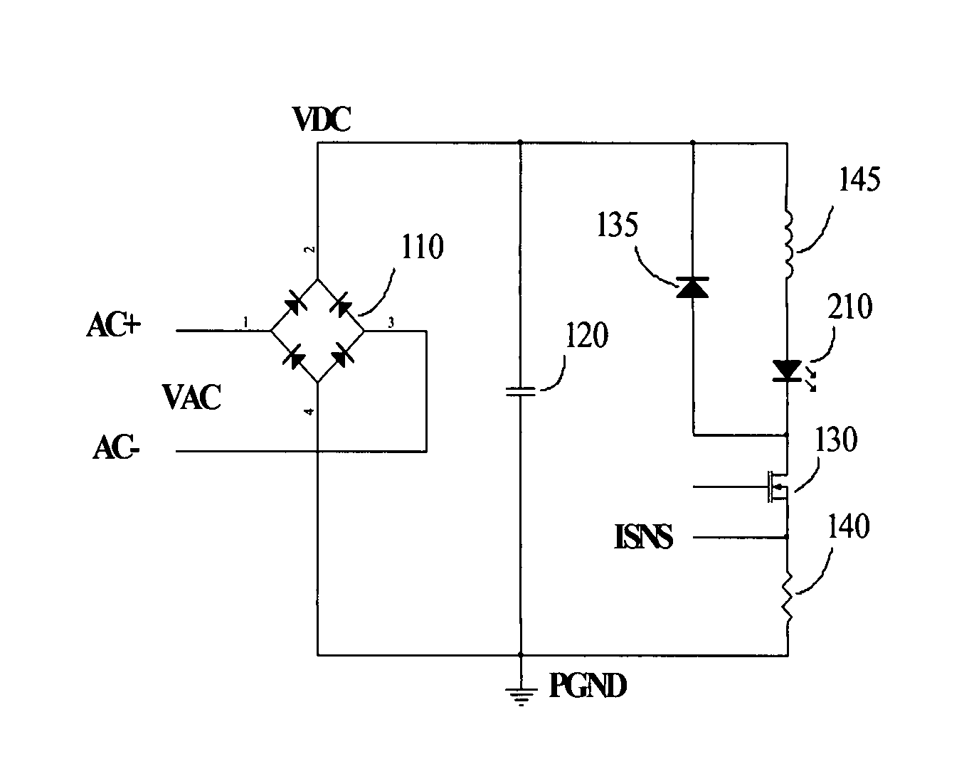
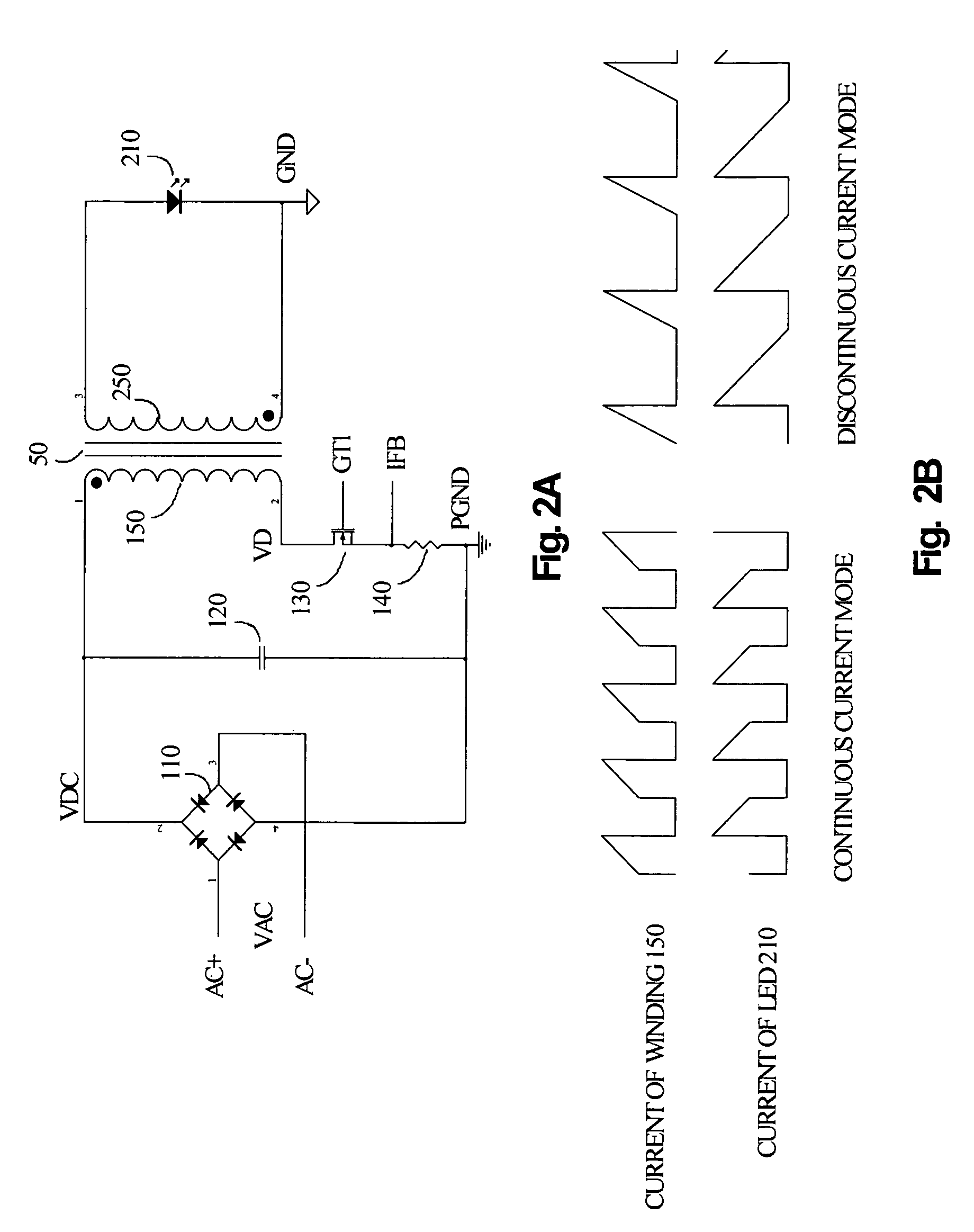
[0027]As described in the last paragraph the purpose of this invention is to find a viable drive solution for LED and OLED devices with low system cost and also enhanced operating efficiency. The first critical part of the invention is innovative concepts in power conversion or power processing. FIG. 2A shows a typical circuit diagram of the concept. In FIG. 2A the components 110, 120, 130, 140, 50 and 210 form the power converter circuit. Note that the essence of this invention is the power conversion process and herein the description of the control circuitry is minimized unless when is necessary for understanding the concept. As can be seen in FIG. 2A, AC input voltage VAC is connected to the AC input terminals AC+ and AC− of the bridge rectifier 110 and converted to a unipolar voltage by the bridge with positive output connected to VDC and the negative output connected at power ground PGND. The AC input VAC can be the mains line voltage, chopped AC voltage from a conventional tr...


PUM


Abstract

A group of novel power conversion concept is developed with this invention for LED and OLED drive applications. The concept utilizes a single power conversion stage to fulfill multiple functions, including Power Factor Correction, DC voltage to DC current conversion, or DC voltage to DC voltage conversion etc. that are necessary for driving LED devices from an AC power input. Multiple dimming control schemes have also been developed to facilitate wide range of application requirements and enable the system to work with different input power format including AC mains power and variable AC voltage from the existing AC dimmer installations.

Description

BACKGROUND OF THE INVENTION[0001]1. Field of the Invention[0002]This invention generally relates to methods of driving LED and OLED devices, and more particularly, to some unique concepts to drive LED and OLED devices with low cost circuits while providing high efficiency power conversion and comprehensive dimming control performance.[0003]2. Description of the Related Art[0004]Light Emitting Diode (LED hereafter) and Organic Light Emitting Diode (OLED hereafter) are bringing revolutionary changes to the lighting industry and the whole world. High efficiency, compact size, long lifetime and minimal pollution etc. are some of the main advantages that provide people elegant lighting solutions and in the meanwhile perfectly into the green power initiative. Because LED and OLED are all made with solid substances, they are also called Solid State Lighting (SSL hereafter) devices. The inherent mechanical robustness of SSL devices together with the features described above also enable them...

Claims


Application Information

Patent Timeline
Patent Type & Authority Patents(United States)
IPC IPC(8): H05B37/02
CPCH05B33/0815H05B33/0827H05B45/38H05B45/385H05B45/46
Inventor FAN, JIANPING
Owner SUNTEC ENTERPRISES
Why Eureka
Try Eureka