
Light emitting diode and display device using the same

Inactive Publication Date: 2008-05-08
ITE TECH INC
View PDF4 Cites 24 Cited by
  • Summary
  • Abstract
  • Description
  • Claims
  • Application Information

AI Technical Summary

Benefits of technology

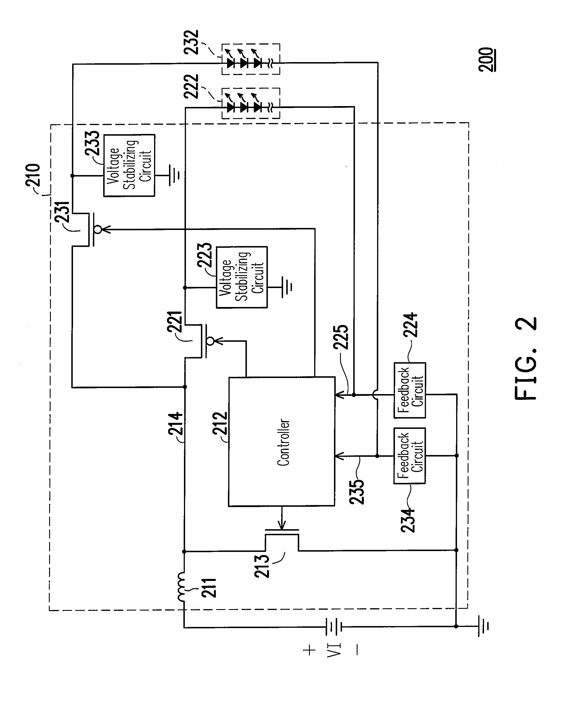
[0011]Accordingly, the present invention is directed to an LED driver capable of driving multiple LED sets, wherein the number of circuit elements used therein is effectively reduced.
[0012]The present invention is also directed to a display device including elements for driving multiple LED sets, and thereby increase element usage efficiency.
[0021]The present invention requires only one main switch, one inductor, and one controller regardless of the number of sets of LEDs to be driven. Thus, the LED driver of the present invention is capable of not only reducing the cost and the bulkiness of the display but also simplify the circuit design of the LED driver circuit. As such, the LED driver is applied in portable consumer electronic products.

Problems solved by technology

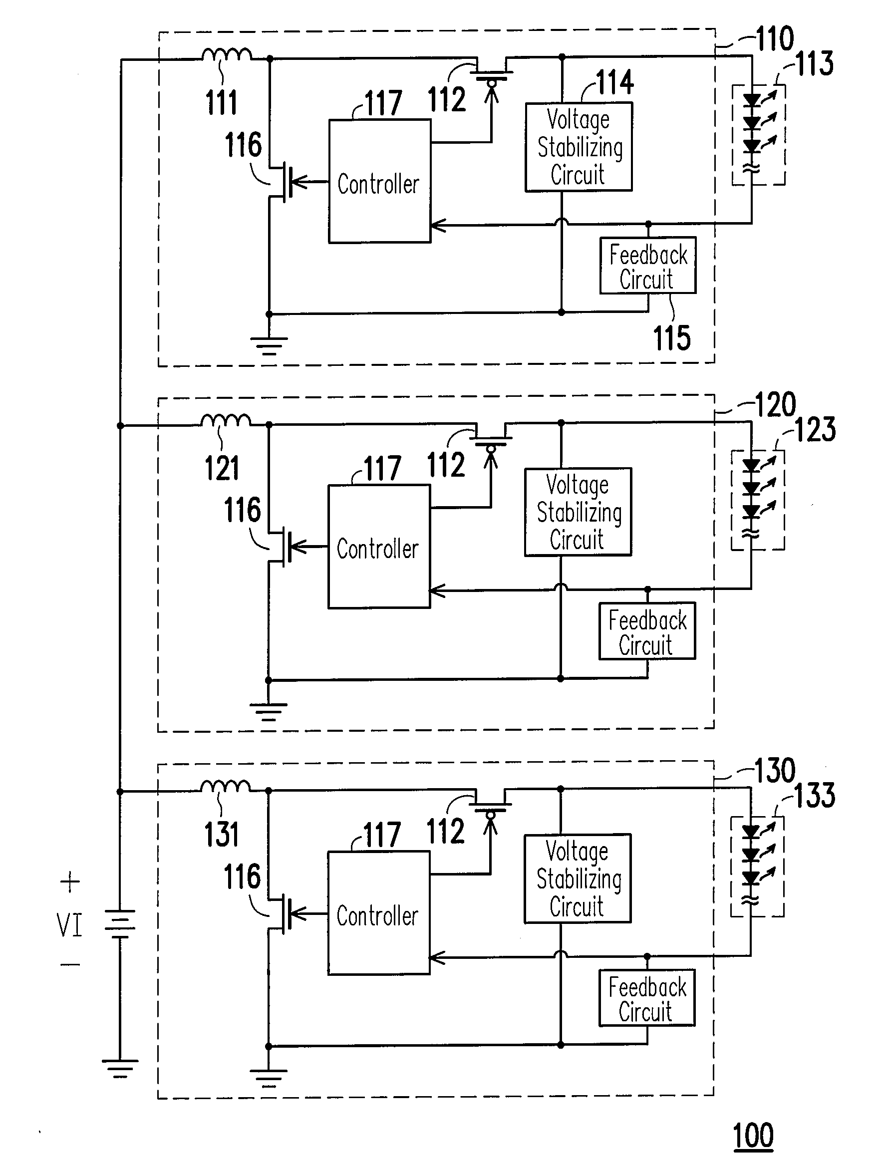
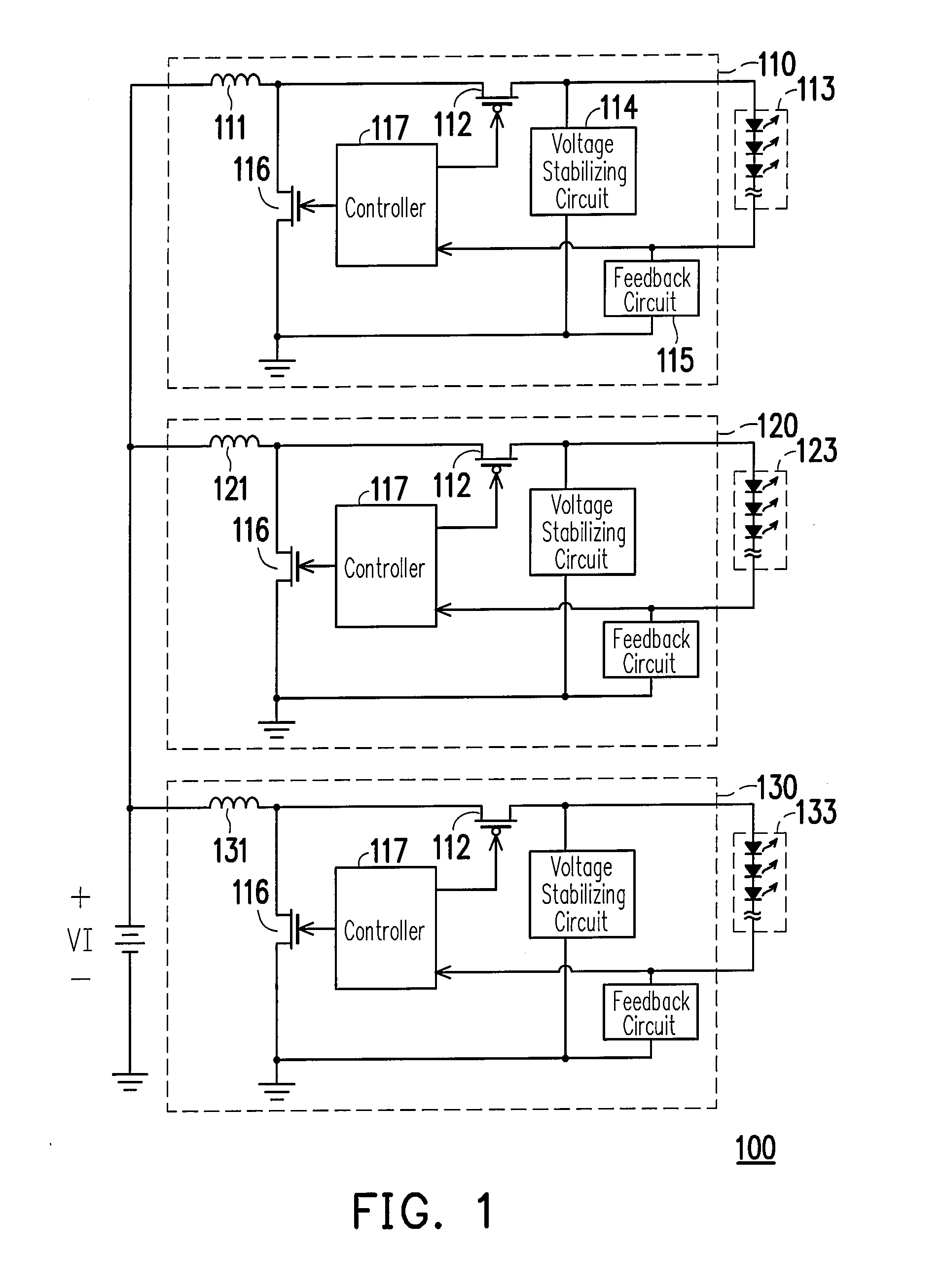
In summary, a disadvantage the convention technology for LED drivers is that it can control a single loop, thus each LED set requires individually designed LED driver.
Such a conventional technology requires relatively large area for circuit.
Accordingly, issues to be considered when designing products having LED drivers are: larger circuit area causes greater product's bulkiness; usage of more LED drivers increase production cost.
Accordingly, conventional technology unfortunately requires too much circuit elements that occupies too much circuit area.
As such, the circuit board thereof becomes very complicated.
When also considering the greater bulkiness, such LED drivers are inconvenient for application.

Method used


Image

  • Light emitting diode and display device using the same
  • Light emitting diode and display device using the same
  • Light emitting diode and display device using the same

Examples


Embodiment Construction

[0026]Reference will now be made in detail to the present preferred embodiments of the invention, examples of which are illustrated in the accompanying drawings. Wherever possible, the same reference numbers are used in the drawings and the description to refer to the same or like parts.

[0027]As described above, the conventional display device requires an independent LED driver circuit for driving an LED set. When the quantity of LED sets increases, correspondingly more number of LED drivers is required. Thus, the number of elements used therein increase accordingly, and circuit elements occupy a larger area on the circuit board. The present invention provides an LED driver including comparatively fewer circuit elements. The LED driver of the present invention will be described below in association with the following preferring embodiments.

[0028]FIG. 2 is a circuit diagram of a display device according to an embodiment of the present invention. Referring to FIG. 2, the display devic...


PUM


Abstract

An LED driver and a display device using the same are disclosed. The LED driver is adapted for driving a first set of LEDs and a second set of LEDs. The LED driver includes an inductor, a main switch, a first switch, a second switch, and a controller. The inductor has a first terminal receiving an input voltage. The main switch is coupled between a second terminal of the inductor and a common level for adjusting a current flowing therethrough. The first switch is coupled between the first set of LEDs and the second terminal of the inductor. The second switch is coupled between the second LEDs and the second terminal of the inductor. The controller is coupled to controlling terminals of the main switch, the first switch, and the second switch respectively for controlling conducting statuses of the main switch, the first switch, and the second switch respectively.

Description

CROSS-REFERENCE TO RELATED APPLICATION[0001]This application claims the priority benefit of Taiwan application serial no. 95140944, filed on Nov. 6, 2006. All disclosure of the Taiwan application is incorporated herein by reference.BACKGROUND OF THE INVENTION[0002]1. Field of the Invention[0003]The present invention generally relates to a display driver, and more particular, to a light emitting diode (LED) driver and a display device using the same.[0004]2. Description of Related Art[0005]Recently, many electronic products are equipped with displays, such as mobile phones, personal digital assistants (PDAs), digital music players, and automobile instrument panels. Types and sizes of the displays are usually designed according to their practical applications. However, almost all displays including liquid crystal displays (LCDs) need backlight modules to provide backlight illumination thereto, and thus designers must design illumination circuits for the displays for allowing users to ...

Claims


Application Information

Patent Timeline
IPC IPC(8): G09G3/32G02F1/133G02F1/13357H01L33/00H05B37/02
CPCH05B33/0866H05B33/0815H05B45/24H05B45/38
Inventor CHOU, YI-CHUNG
Owner ITE TECH INC
Learn More