LED driving circuit having dimming circuit

a driving circuit and led technology, applied in the direction of electric variable regulation, process and machine control, instruments, etc., can solve the problems of slow response rate and low color reproducibility, inability to miniaturize, and environmental pollution, so as to increase the ‘ and decrease the ‘

Inactive Publication Date: 2006-11-23
SAMSUNG ELECTRO MECHANICS CO LTD
View PDF6 Cites 182 Cited by
  • Summary
  • Abstract
  • Description
  • Claims
  • Application Information

AI Technical Summary

Benefits of technology

[0016] Preferably, the PWM driver is a PWM IC having a comp terminal which increases the ‘on’ duration of the switching pulse when an applied voltage is increased and which decreases the ‘on’ duration of the switching pulse when the applied voltage is decreased, and the control signal from the PWM controller is applied to the comp terminal.

Problems solved by technology

Thus, it has drawbacks in that it is prone to environmental pollution, has a slow response rate and low color reproducibility, and is inappropriate for miniaturization of an LCD panel.
However, this method also bears a problem in which the voltage detection resistor Rs has to use a wattage resistor, which complicates variation.
However, the voltage detection resistors Rs of the driving circuits have different resistance values in practice, adversely affecting the adjustment of luminance, regulation of color coordinates and resultant color uniformity.

Method used


Image

  • LED driving circuit having dimming circuit
  • LED driving circuit having dimming circuit
  • LED driving circuit having dimming circuit

Examples


Embodiment Construction

[0025] Preferred embodiments of the present invention will now be described in detail with reference to the accompanying drawings. The invention may, however, be embodied in many different forms and should not be construed as limited to the embodiments set forth herein. Rather, these embodiments are provided so that this disclosure will be thorough and complete, and will fully convey the scope of the invention to those skilled in the art. In the drawings, the shapes and dimensions are exaggerated for clarity and the same reference numerals are used throughout to designate the same or similar components.

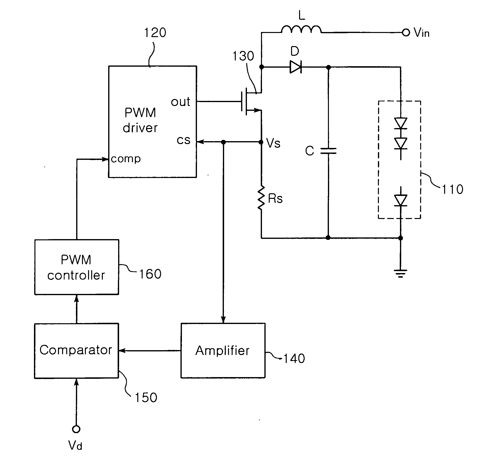
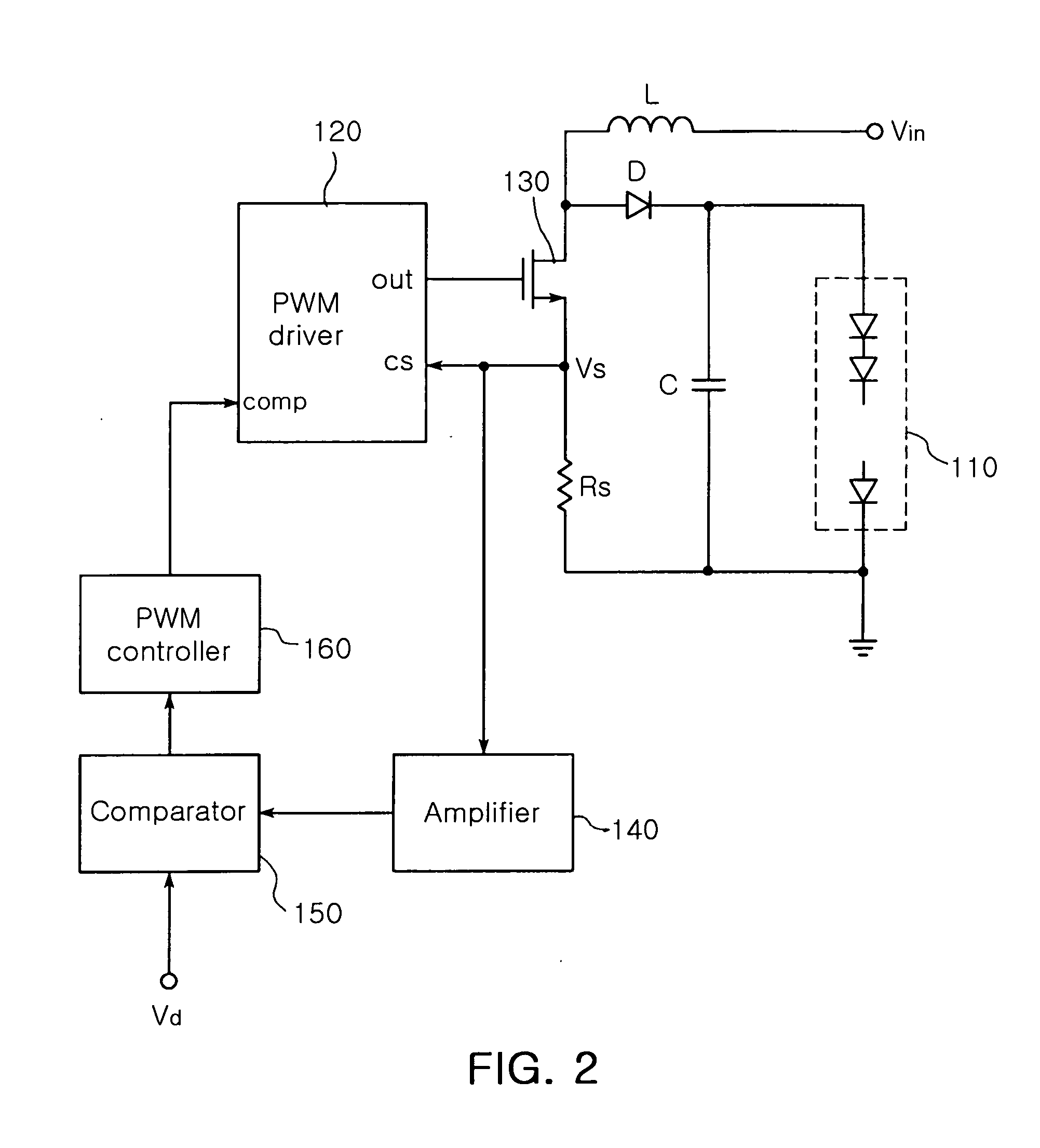
[0026]FIG. 2 is a block diagram illustrating an LED driving circuit having a dimming circuit according to an embodiment of the present invention. FIG. 2 illustrates an LED driving circuit having a boost DC-DC converter but the present invention is not limited thereto, and is applicable to LED driving circuits having any kind of DC-DC converters adopting the PWM method. With reference...


PUM


Abstract

The invention relates to an LED driving circuit having a dimming circuit, which includes a PWM driver for providing a switching pulse having a width adjustable according to a voltage value detected by a voltage detecting resistor to control on / off durations of a switch. The circuit also includes a comparator for comparing the voltage value detected from the voltage detection resistor with a predetermined dimming voltage value, and a PWM controller for generating a control signal to increase the ‘on’ duration of the switching pulse outputted from the PWM driver if a comparison value from the comparator is increased, and to decrease the ‘on’ duration of the switching pulse outputted from the PWM driver if the comparison value from the comparator is decreased. The width of the switching pulse outputted from the PWM driver is controlled according to the predetermined dimming voltage value to adjust luminance of an LED.

Description

CLAIM OF PRIORITY [0001] This application claims the benefit of Korean Patent Application No. 2005-41526 filed on May 18, 2005, in the Korean Intellectual Property Office, the disclosure of which is incorporated herein by reference. BACKGROUND OF THE INVENTION [0002] 1. Field of the Invention [0003] The present invention relates to a light emitting diode (LED) driving circuit having a dimming circuit, and more particularly, which compares a detected voltage value provided to a PWM driver with a predetermined dimming voltage, and according to a difference between these two values, controls an ‘on’ duration of a switching pulse outputted from the PWM driver, thereby simply adjusting luminance of an LED without using a variable resistor. [0004] 2. Description of the Related Art [0005] A general Cold Cathode Fluorescent Lamp (hereinafter referred to as CCFL) for a backlight of a Liquid Crystal Display (hereinafter referred to as LCD) uses mercury gas. Thus, it has drawbacks in that it i...

Claims


Application Information

Patent Timeline
Patent Type & Authority Applications(United States)
IPC IPC(8): H05B37/02H01L33/00
CPCH05B33/0815Y02B20/346H05B33/0863H05B33/086H05B45/20Y02B20/30H05B45/3725H05B45/38H05B45/10G09G3/36G02F1/133
Inventor LEE, SANG YUN
Owner SAMSUNG ELECTRO MECHANICS CO LTD
Why Eureka
Try Eureka