
Advanced system for electrochemical cell

a technology of electrochemical cells and advanced systems, applied in the field of electrochemical systems, can solve the problems of mechanical weakening of the conductance membrane, and achieve the effects of increasing the transport of water, and increasing the ‘n’ of the polar species

Pending Publication Date: 2021-12-30
XERGY INC
View PDF0 Cites 0 Cited by
  • Summary
  • Abstract
  • Description
  • Claims
  • Application Information

AI Technical Summary

Benefits of technology

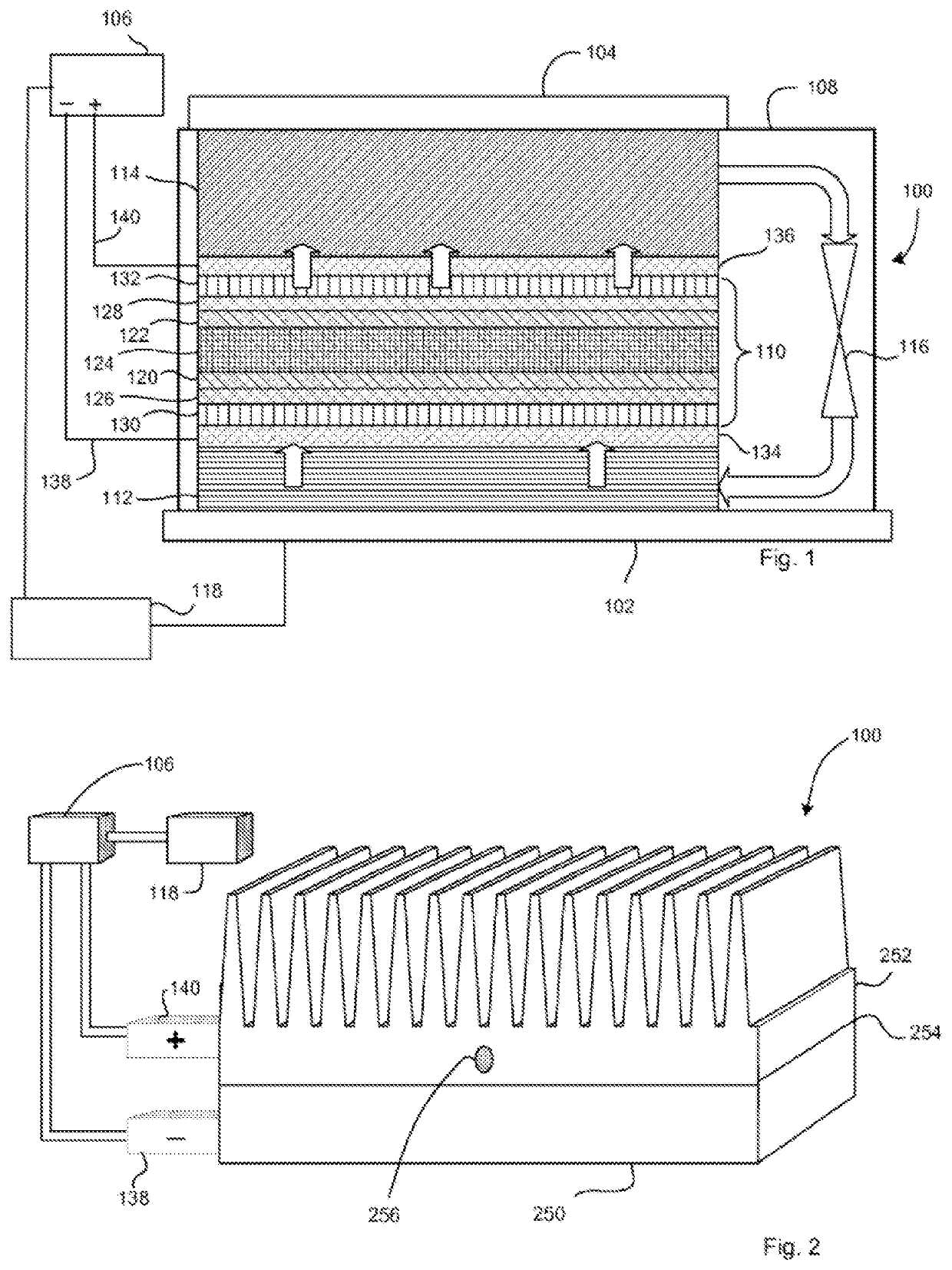
The invention is about improving the performance of electrochemical compressors by modifying the components used in the system. The invention introduces a flow component that increases the transport of water or polar species through the ion conducting media, thus improving the performance of the compressor. The flow component can be a surfactant or a weak solvent for the ion conducting media, which can cause the media to swell and improve water transport. The invention also suggests using membranes with higher conductance and thinner membranes for the compressor. Additionally, the invention proposes modifying gas diffusion electrodes to render them hydrophilic and using different electrode formulations to improve hydrophobicity. The invention also includes a condenser, evaporator, and expansion valve for the system. Overall, the invention provides a more efficient and effective electrochemical compressor for refrigeration systems.

Problems solved by technology

Usually such higher conductance membranes are mechanically weaker, and thus need to be reinforced with a substrate to provide the strength required in operation, and under a pressure differential, in the compressor.

Method used


Image

  • Advanced system for electrochemical cell
  • Advanced system for electrochemical cell
  • Advanced system for electrochemical cell

Examples


second embodiment

[0128]In addition, there is clearly a relationship between the water migration rates in membranes and the degree of acidity in the membranes. This can be quantified in practical terms with ionic conductance measurements. Higher water presence, and larger swelling in the water channels clearly results in higher conductance, and therefore in effect ‘larger’ water shells surrounding the proton. Thus in this invention, the electrochemical compressor is modified to employ membranes with much higher conductance—i.e. lower equivalent weight, EW, but also thinner membranes. Usually such higher conductance membranes are mechanically weaker, and thus need to be reinforced with a substrate to provide the strength required in operation (and under a pressure differential) in the compressor.

third embodiment

[0129]In a third embodiment, gas diffusion electrodes are modified to render them hydrophilic; not directly as a result of additives in the refrigerant formulation, but by controlling the electrode formulation itself to render it hydrophilic. It is typical in fuel cell type electrodes to mix in components to improve hydrophobicity, such as PTFE dispersions or high molecular weight ionomers. Therefore electrode formulations are provided that are considerably different to fuel cell systems—and therefore novel and inventive and counter intuitive for use in electrochemical compressors.


PUM

PropertyMeasurementUnit
surface energyaaaaaaaaaa
surface tensionaaaaaaaaaa

Abstract

A high water transfer electrochemical compressor is described having a ‘n’ transfer of water through the ion conducting membrane of greater than one. This may be accomplished by reducing the equivalent weight of the ion conducting polymer, such as an ionomer to less than about 900 and / or by reinforcing the low equivalent weight ionomer with a support material, such as an expanded polytetrafluoroethylene. This may be accomplished by making components of the electrochemical cell hydrophilic including the electrodes and / or gas diffusion media. This may be accomplished by adding a flow component to a feed fluid or refrigerant, such as an alcohol, acid, or acetone, for example. A flow component may modify an electrode and / or the ion conducting media, by rendering them hydrophilic. A flow component may swell an ion conducting media enable high transport of the working fluid.

Description

CROSS REFERENCE TO RELATED APPLICATIONS[0001]The application is a continuation of U.S. application Ser. No. 15 / 360,914 filed on Nov. 23, 2016, which is a continuation of U.S. application Ser. No. 15 / 289,220 filed on Oct. 10, 2016, entitled Electrochemical Heat Transfer System and currently pending, which is a continuation of U.S. application Ser. No. 13 / 029,006 filed on Feb. 16, 2011 entitled “Electrochemical Heat Transfer System”, now issued as U.S. Pat. No. 9,464,822 on Oct. 11, 2016, which is a continuation-in-part of U.S. application Ser. No. 12 / 771,620, filed on Apr. 30, 2010 and entitled “Self-Contained Electrochemical Heat Transfer System”, now issued as U.S. Pat. No. 8,627,671 issued on Jan. 14, 2014, which claims the benefit of U.S. provisional patent application No. 61 / 215,131 filed on May 1, 2009, and U.S. application Ser. No. 13 / 029,006 claims priority to U.S. provisional patent application No. 61 / 305,410, filed on Feb. 17, 2010 and entitled “Electrochemical Heat Pump Sy...

Claims


Application Information

Patent Timeline
Patent Type & Authority Applications(United States)
IPC IPC(8): F25B1/00C09K5/04
CPCF25B1/00C09K5/041F25B2400/07Y02P20/129F25B1/005F25B23/00
Inventor BAHAR, BAMDADPARMELEE, WILLIAM
Owner XERGY INC
Learn More