Eureka AIR delivers breakthrough ideas for toughest innovation challenges, trusted by R&D personnel around the world.

Sealed liner system for interment vessels or containers

a liner system and interment vessel technology, applied in the field of sealing the interior can solve the problems of affecting the service life the inability to meet the needs of the interment vessel, and the type of seal inevitably breaks down, so as to prevent the leakage of fluids, prevent the infiltration of fluids, and improve the service life.

Inactive Publication Date: 2005-06-07
PANGEAA INTERMENT SYST
View PDF71 Cites 11 Cited by
  • Summary
  • Abstract
  • Description
  • Claims
  • Application Information

AI Technical Summary

Benefits of technology

[0004]It is an object of the present invention to provide a system for sealing the interior of an interment vessel or container, which prevents leakage of fluids from the interior of the vessel or container and which prevents infiltration of fluids from the exterior of the vessel or container. It is a further object of the invention to provide such a system which is relatively simple in its components and construction, and which can be relatively easily carried out after the remains have been placed into the vessel or container. It is a further object of the invention to provide such a system having a sealing arrangement which ensures a positive, integral seal. It is a further object of the invention to provide a sealed interment container or vessel as well as a method of sealing the interior of an interment container or vessel, which is capable of being employed in combination with conventional interment containers or vessels, such as caskets or vaults.
[0005]In accordance with the general principle of the present invention, an interment vessel or container has an exterior shell and a sealed internal liner. The exterior shell is of two-piece construction, typically including a lower member or base and an upper member, e.g. a top or lid, which is adapted to overlie the lower member. In the case of a conventional burial vault, the lower member is in the form of the bottom section of the vault that defines a cavity or recess which is adapted to receive a casket, and the upper member is in the form of a concrete lid that engages the upper end of the base to form the closed interior of the vault. Similarly, in the case of a casket, the lower member or base is in the form of the bottom or lower section of the casket, which defines a recess or cavity adapted to receive the body of the deceased. The upper member is in the form of a top or lid that engages the upper end of the lower member, to form the closed interior of the casket. In either application, the invention contemplates a liner construction that is sealed about the contents of the vessel or container, to prevent outward leakage of fluids from within the vessel or container and inward infiltration of fluids into the vessel or container.
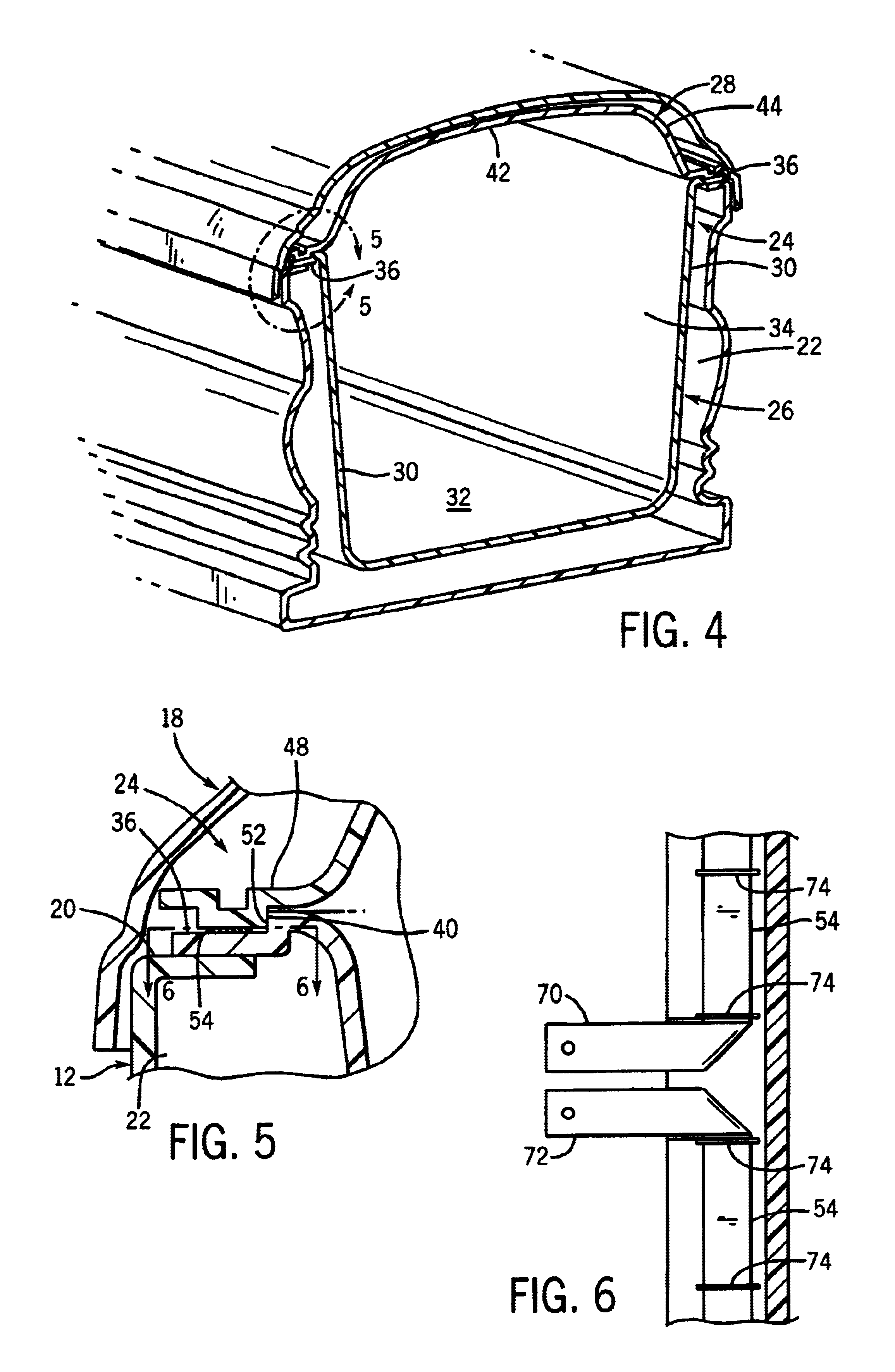
[0007]In one embodiment, the lower section of the liner defines an upper flange, and the upper section of the liner defines a lower flange which is adapted to engage the upper flange of the lower member. The upper and lower sections are formed of a thermoplastic material, and the flanges are adapted to be sealed together to form a unitary flange that extends about the periphery of the liner. In a preferred form, the flanges are sealed together by means of a peripherally extending strip of electrically conductive and resistive material disposed between the upper and lower flanges. Electrical current is applied to the strip of material to heat the strip, which functions to heat the surrounding areas of the upper and lower flanges. The thermoplastic material of the upper and lower flanges liquefies and flows together about the strip to unite the upper and lower flanges, and the current applied to the strip is then cut off so that the strip and the material of the upper and lower flanges subsequently cools, which results in solidification of the liquefied material of the flanges. The upper and lower flanges are thus bonded or sealed together to form a unitary integral seal flange about the entire periphery of the liner. The integral sealed flanges function to prevent leakage of the contents of the liner and to prevent infiltration of fluids into the liner.

Problems solved by technology

Interment vessels, such as caskets and vaults, present significant long-term problems caused by the inability to effectively seal the interior of the vessel against leakage and infiltration.
Over time, this type of seal inevitably breaks down.
In addition, it is common for the concrete material of the vault to crack under pressure from the surrounding earth or due to freeze-thaw pressures.
In either case, the integrity of the vault is compromised, which can result in infiltration of ground water and other fluids, as well as outward leakage of fluids and other materials from the decomposing contents of the vault.
Such fluid infiltration and leakage can have serious adverse effects on ground water and other aspects of the surrounding environment.
These are serious drawbacks associated with conventional burial and interment vessels, that result in difficult problems which have either been ignored or which have involved troublesome and expensive solutions.

Method used


Image

  • Sealed liner system for interment vessels or containers
  • Sealed liner system for interment vessels or containers
  • Sealed liner system for interment vessels or containers

Examples


Embodiment Construction

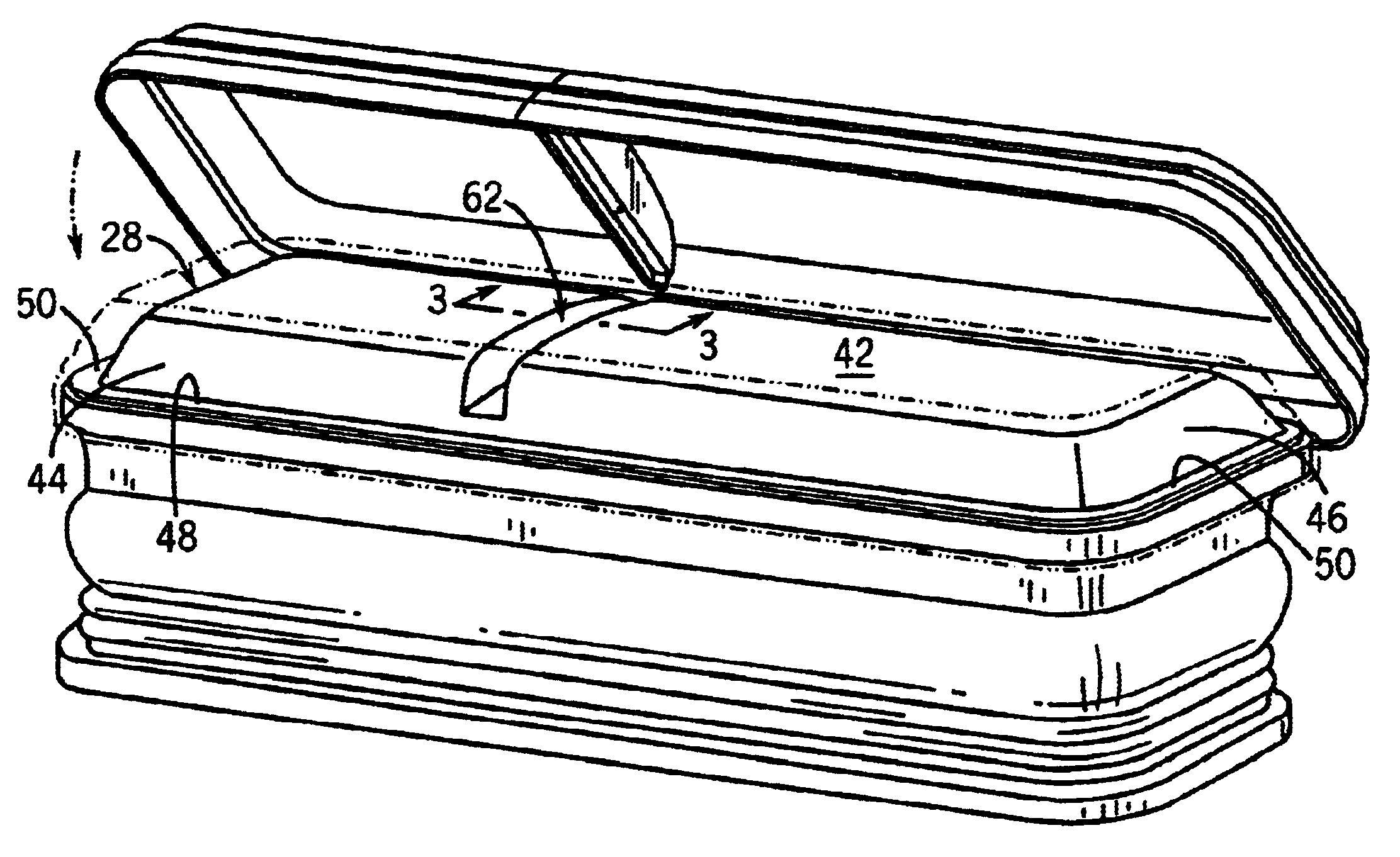
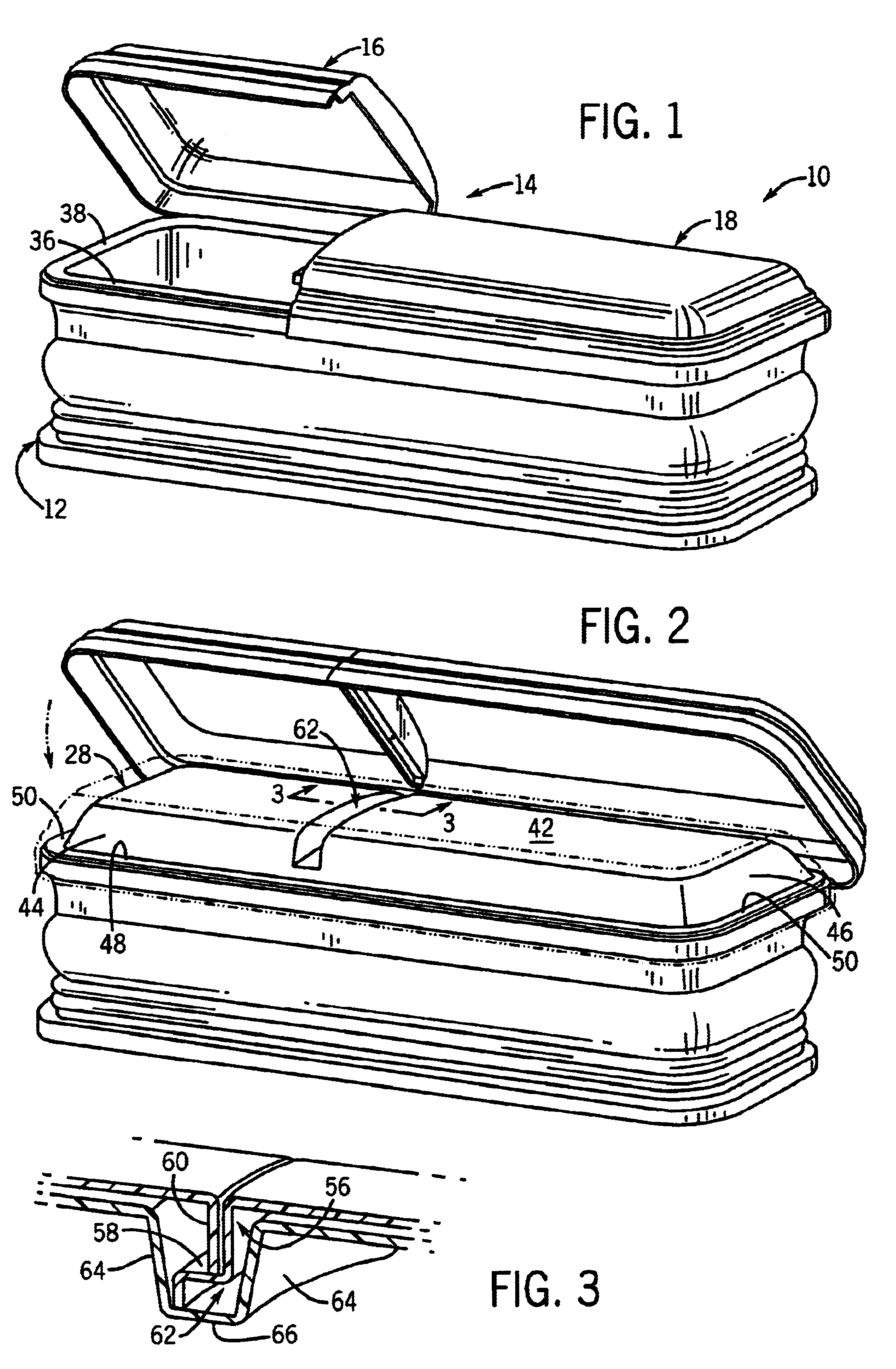
[0022]Referring to FIG. 1, an interment vessel or container in the form of a casket 10 generally includes a bottom or lower member 12 which defines a bottom wall and a series of upstanding side walls which cooperate to define an internal recess or cavity adapted to receive the remains of a deceased. Casket 10 further includes a top or upper member 14 which is adapted to overlie and enclose the recess or internal cavity of lower member 12. In the illustrated embodiment, upper member 14 has a split construction, and includes a head section 16 and a foot section 18, each of which is hinged to lower member 12 for providing pivoting movement between open and closed positions. It is understood, however, that upper member 14 may be of a one-piece construction as opposed to the illustrated split construction. It is further understood that upper member 14 may be separate from lower member 12 so as to be engageable with lower member 12 by placing the upper member on the lower member, or that ...


PUM

PropertyMeasurementUnit
Electrical resistanceaaaaaaaaaa
Electrical conductoraaaaaaaaaa
Electrical currentaaaaaaaaaa

Abstract

An interment container includes upper and lower members that define an internal cavity. The remains of a deceased are placed within a liner adapted to be positioned within the internal cavity. The liner is peripherally sealed about the remains of the deceased, to prevent leakage of fluids from within the liner and infiltration of fluids into the liner. The liner includes lower and upper sections that define facing peripheral flanges which are sealed together by positioning a heating member between facing surfaces of the flanges, and imparting heat to the heating member so as to liquefy the adjacent material of the flanges. The liquefied material flows together about the heating member and the heating member is then cooled, such that the liquefied portions of the flanges solidify to integrally seal the flanges together.

Description

BACKGROUND AND SUMMARY OF THE INVENTION[0001]This invention relates to interment vessels or containers such as caskets or vaults, and more particularly to a system for sealing the interior of an interment vessel.[0002]Interment vessels, such as caskets and vaults, present significant long-term problems caused by the inability to effectively seal the interior of the vessel against leakage and infiltration. In a conventional concrete vault, it is common to place an asphaltic sealing compound between the base and the lid of the vault. Over time, this type of seal inevitably breaks down. In addition, it is common for the concrete material of the vault to crack under pressure from the surrounding earth or due to freeze-thaw pressures. In either case, the integrity of the vault is compromised, which can result in infiltration of ground water and other fluids, as well as outward leakage of fluids and other materials from the decomposing contents of the vault. Such fluid infiltration and le...

Claims


Application Information

Patent Timeline
IPC IPC(8): A61G17/00A61G17/04
CPCA61G17/00A61G17/04A61G2017/042A61G17/007A61G17/042A61G17/036A61G17/0136A61G17/0106
Inventor SEVEY, DOUGLAS L.
Owner PANGEAA INTERMENT SYST
Why Eureka
Eureka Blog
Learn More