Crossbow with inset foot claw

Active Publication Date: 2005-06-07
BARNETT OUTDOORS
View PDF6 Cites 70 Cited by
  • Summary
  • Abstract
  • Description
  • Claims
  • Application Information

AI Technical Summary

Benefits of technology

[0003]In view of the foregoing, it is an object of the present invention to provide a crossbow in which the overall length, including the foot stirrup, is reduced. To achieve this and other objects of the invention that will become apparent to those skilled in the art, this invention provides a crossbow having a stock with oppose

Problems solved by technology

However, some users of shorter stature have experienced difficulty in bending over the combined l

Method used


Image

  • Crossbow with inset foot claw
  • Crossbow with inset foot claw
  • Crossbow with inset foot claw

Examples


Example

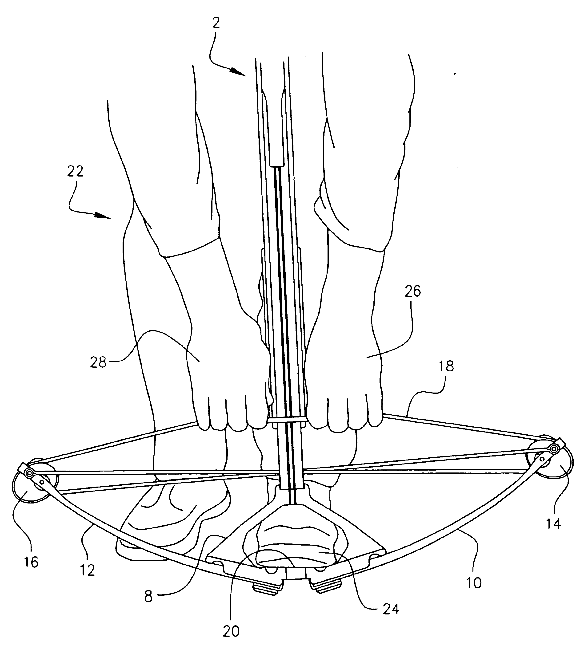
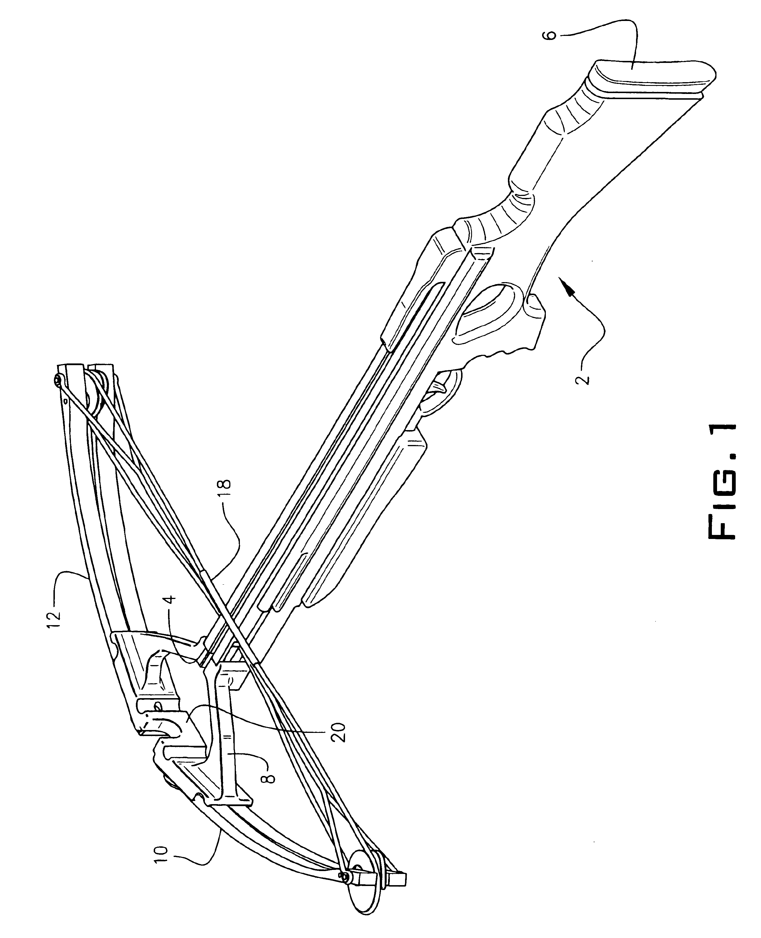
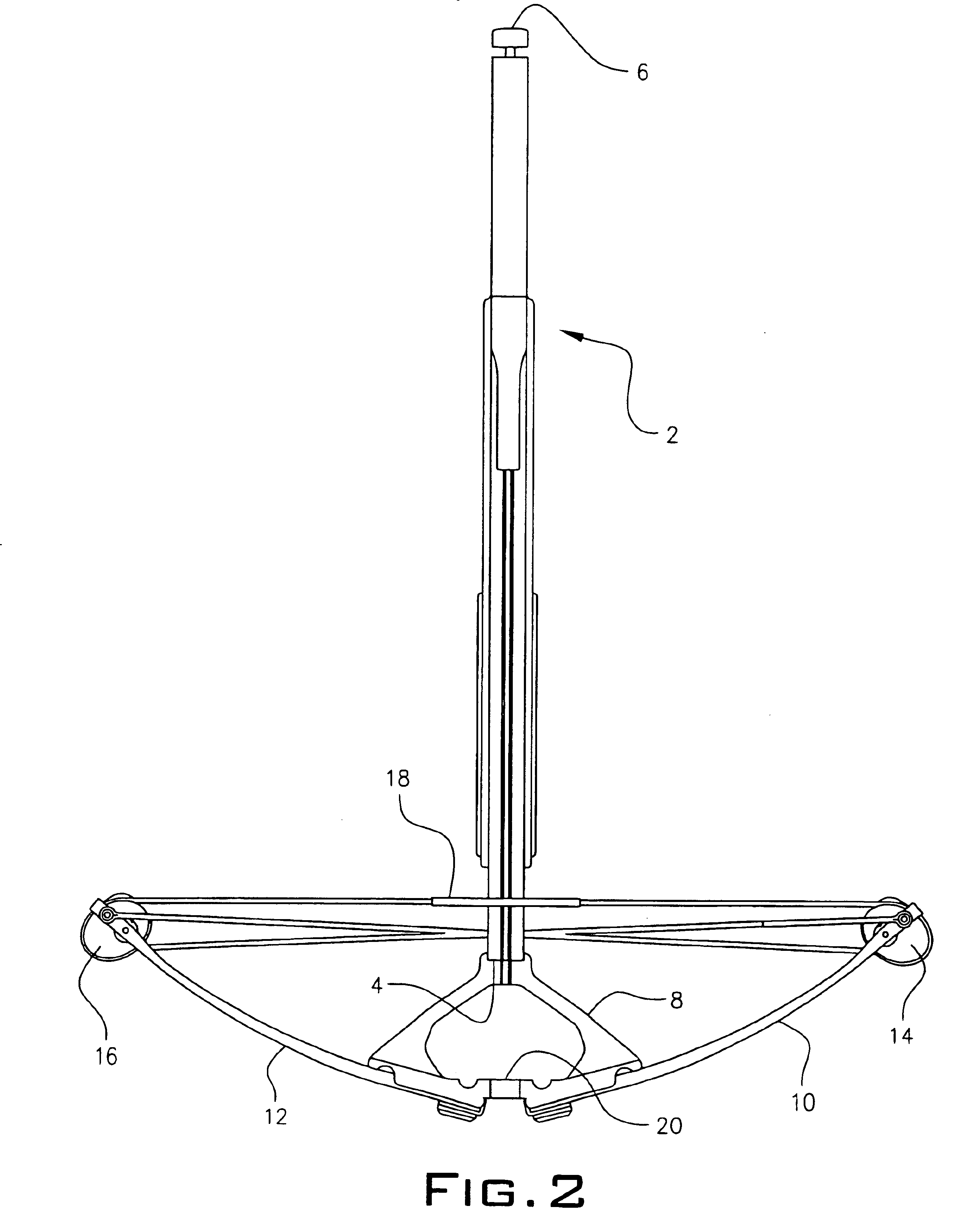
[0008]A preferred embodiment of the crossbow of the present invention is illustrated in FIGS. 1 through 3. FIG. 1 is a rear perspective view of such a crossbow, in which reference numeral 2 refers generally to the stock of the crossbow, which stock includes a forward end 4 and a rearward end 6. The stock may be fabricated of any suitable material, which may include, without limitation, wood and synthetic resins. To the forward end 4 of the stock 2 is affixed a riser or bracket 8, suitably fabricated of a metal, such as aluminum of steel, or the like, or of a rigid synthetic resin. To this riser 8 is affixed the prods 10 and 12 that comprise the bow portion of the crossbow. These prods 10 and 12 may be affixed to the riser 8 by any suitable means, such as threaded fasteners or clamps, known to those skilled in the art. As shown more clearly in FIGS. 2 and 3, a preferred embodiment of the bow portion of the apparatus may include, adjacent the outermost extremities of the prods 10 and ...


PUM


Abstract

A crossbow having a stock with opposed longitudinal ends including a forward end to which is mounted a bow and a rearward end for engaging the shoulder of a user, includes a foot stirrup mounted to the stock forward end and interposed between the stock forward end and the bow, such that a user's foot is insertable into such stirrup to support the crossbow for cocking.

Description

BACKGROUND OF THE INVENTION[0001]This invention relates generally to a crossbow having a foot stirrup for use in cocking the crossbow, which foot stirrup is inset behind the bow prod.[0002]Crossbows conventionally have included a foot stirrup for use in cocking. This is necessary so that the user can place his foot in the stirrup to hold the front of the crossbow against the ground while the user pulls the bow string back to a cocked position with his or her hands. Such prior art stirrups have conventionally extended out the front end of the stock of the crossbow, thus being positioned forward of the bow prods. For many users, particularly those who are tall, such an arrangement is satisfactory, in that they can bend over the crossbow stock and pull the string into the cocked position. However, some users of shorter stature have experienced difficulty in bending over the combined length of the crossbow stock and the forwardly projecting stirrup to grasp the string for cocking. For t...

Claims


Application Information

Patent Timeline
IPC IPC(8): F41B5/00F41B5/12
CPCF41B5/123
Inventor BARNETT, DAVID A.
Owner BARNETT OUTDOORS
Why Eureka
Try Eureka