Cushion mount with slide device

Inactive Publication Date: 2005-06-07
TAKATA RESTRAINT SYST
View PDF31 Cites 9 Cited by
  • Summary
  • Abstract
  • Description
  • Claims
  • Application Information

AI Technical Summary

Benefits of technology

[0005]In one aspect, a deployment guide for a vehicle occupant protection device is provided. The deployment guide has a housing with a channel having a substantially smooth interior and a slotted side. A guide member is also provided, is slidably retained in the channel, and includes an extension protruding from the slotted side of the channel. The extension is attachable to a restraint device deployable laterally of a vehicle occupant. An actuator is also provided, and is operable to drive the guide member from a first end of the channel toward a second end. A driving of the guide member facilitates deployment of the restraint device, and supplies at least a longitudinal tensioning force to the restraint device to provide lateral support thereto.
[0006]In another aspect, a side impact restraint apparatus for cushioning a vehicle occupant during a collision is provided. The apparatus includes an inflatable restraint cushion mounted inside the vehicle adjacent a side door, and deployable in a direction away from the roof rail of the vehicle. A guide member is movably mounted in a partially closed guide track fixed to an upright vehicle pillar. The guide member includes a portion extending through a slot in the guide track and conne

Problems solved by technology

Due to the limited vehicle structure that separates an occupant from a rapidly moving body impacting the side of the vehicle, occupants may sustain much greater injuries in side-impact events than front or rear impacts.
Moreover, the forces generated in side-impact or vehicle rollover events may actually cause the occupant to be ejected from the side of the vehicle.
Some vehicles, due to their structure as well as a possible increased rollover risk, present particular problems in this area.
Where inflatable cu

Method used


Image

  • Cushion mount with slide device
  • Cushion mount with slide device
  • Cushion mount with slide device

Examples


Example

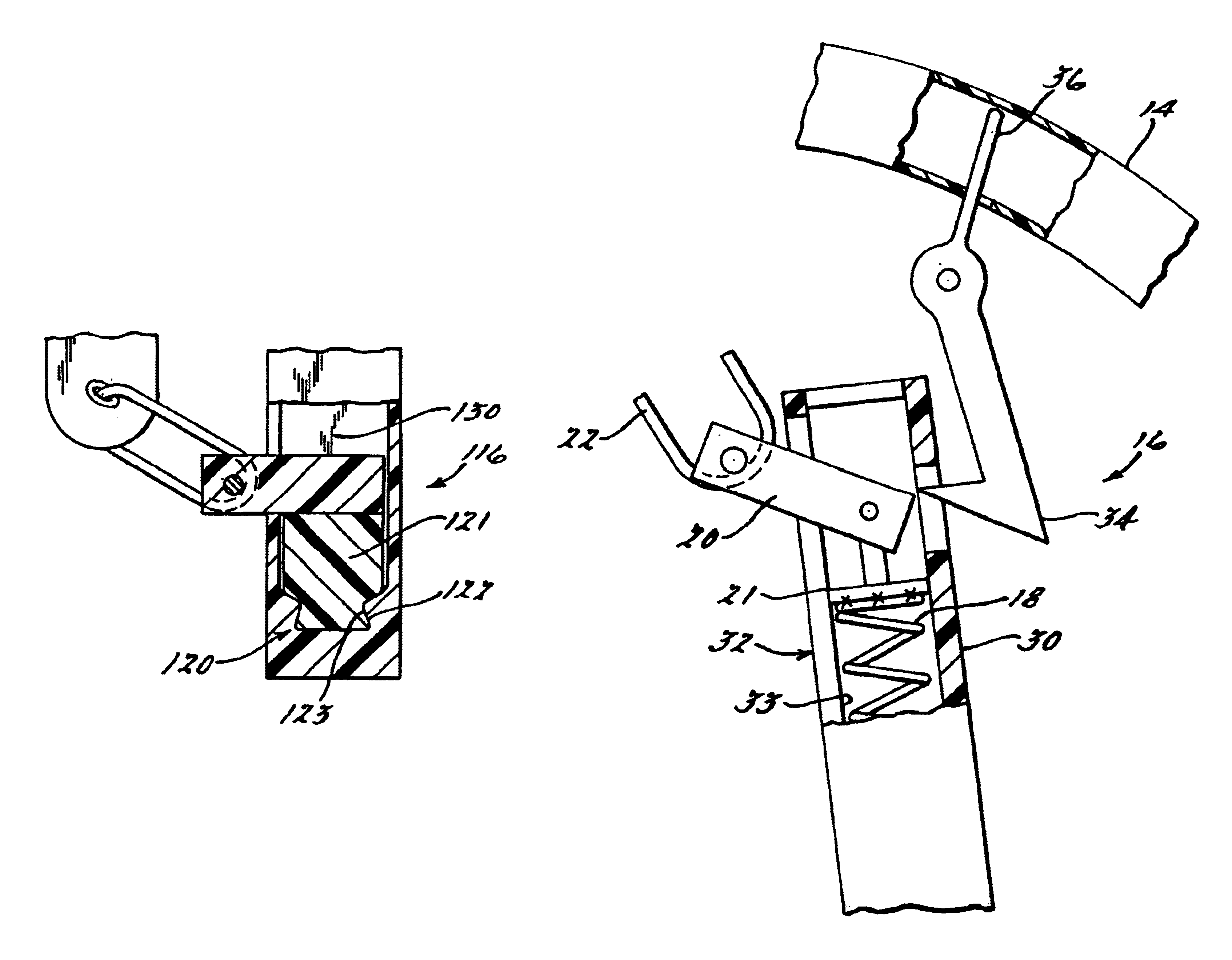
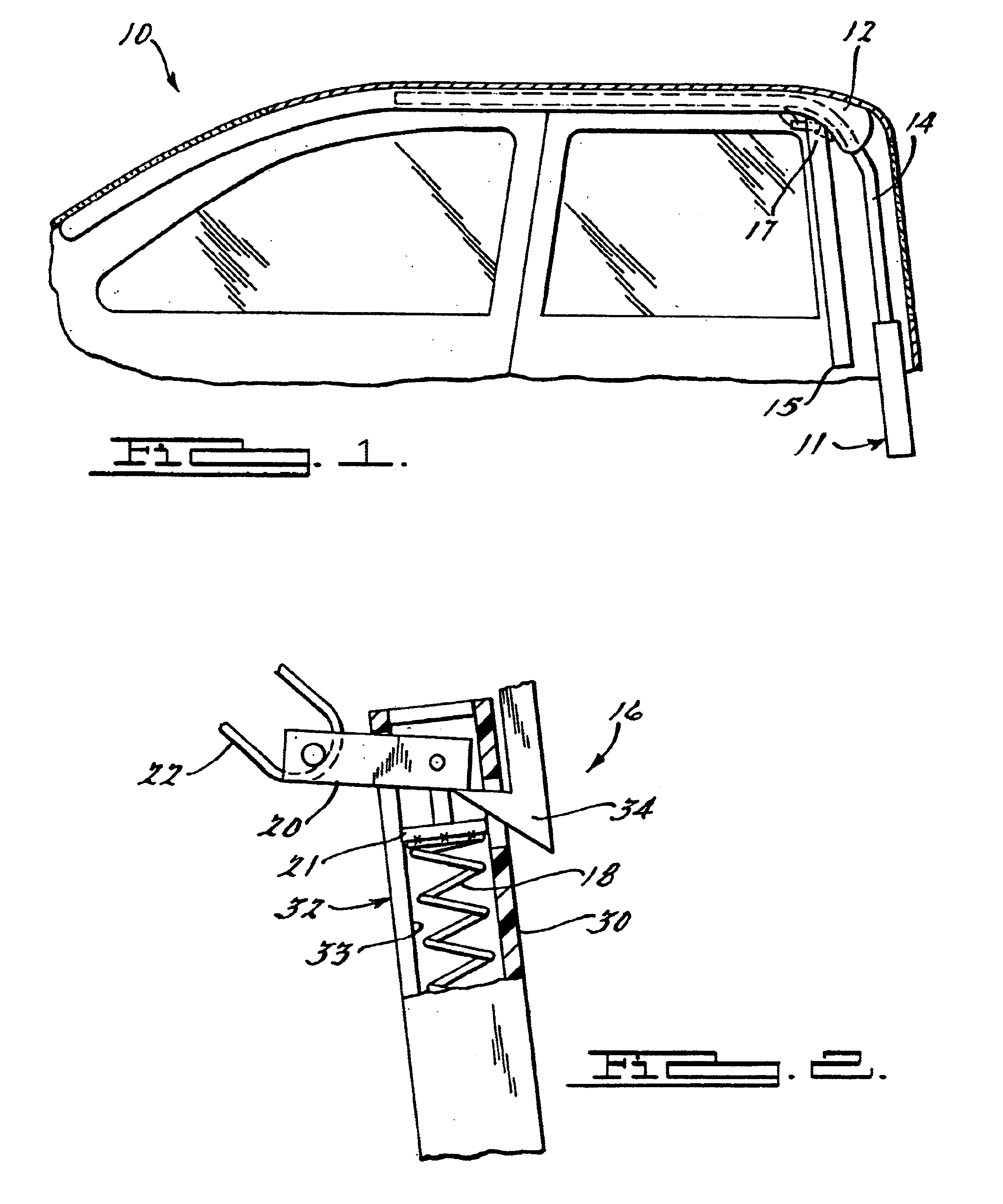
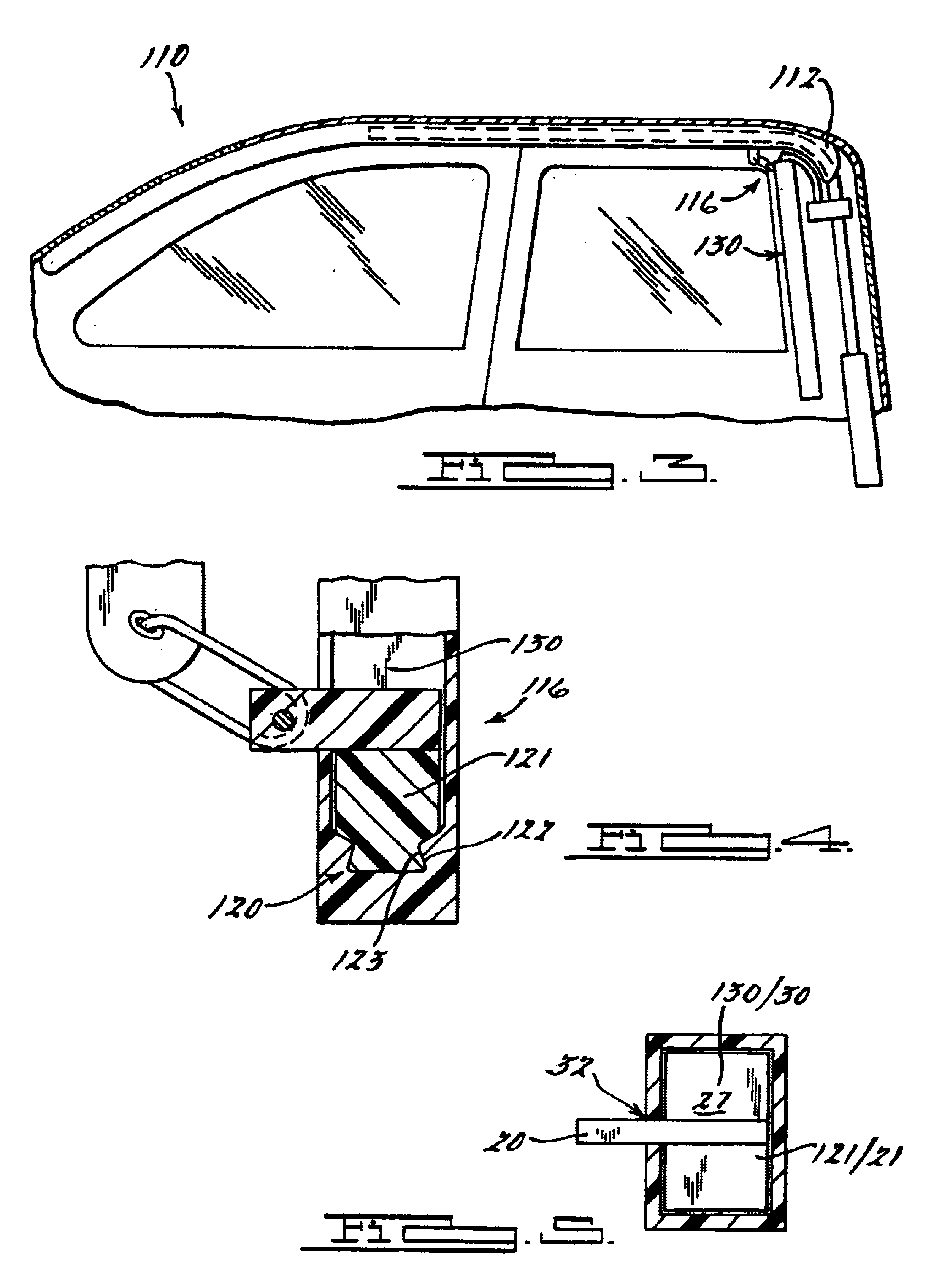
[0014]Referring to FIG. 1, there is shown a side view of an occupant protection apparatus 10 according to a preferred embodiment of the present invention. Apparatus 10 is directed to assisting in the deployment and lateral support of a side impact restraint device. Apparatus 10 actively assists the restraint device in rapidly and accurately deploying in a direction away from a vehicle roof rail. Once deployed, the apparatus provides lateral support to the restraint, lessening the likelihood that it will be displaced or forced out through the vehicle window during a crash or rollover event, and likewise reducing the risk of occupant ejection and / or injury. Apparatus 10 includes a restraint device 12, which is preferably a conventional inflatable airbag or cushion, shown in its folded / stored condition, as it would appear in a de-activated state prior to a crash. It should be appreciated that embodiments are contemplated in which a non-inflatable curtain is utilized rather than an airb...


PUM


Abstract

A restraint apparatus for protecting a vehicle occupant in a side impact or rollover event. The restraint apparatus includes a deployment guide that includes a housing having a channel with a substantially smoothed interior and longitudinal slot. A guide member is slidably retained in the channel and has an extension protruding from the slotted side of the channel. The extension is attachable to a restraint device deployable laterally of a vehicle occupant. An actuator is provided and is operable to drive the guide member from a first end of the channel toward a second end. A driving of the guide member facilitates deployment of the restraint device and supplies at least a longitudinal tensioning force to the restraint device to provide lateral support thereto.

Description

TECHNICAL FIELD[0001]The present invention relates generally to side impact restraint devices, and more particularly to such a device having a cushion tethered to an actuatable slide device.BACKGROUND OF THE INVENTION[0002]Supplemental restraint devices have become commonplace in vehicles in recent years and engineering and design efforts have increasingly focused on such devices deployable along vehicles' interior sides. In the event of a side impact or vehicle rollover event, a curtain or inflatable cushion is rapidly positioned between the vehicle passenger and the window / door of the vehicle. Due to the limited vehicle structure that separates an occupant from a rapidly moving body impacting the side of the vehicle, occupants may sustain much greater injuries in side-impact events than front or rear impacts. The energy absorbed by the vehicle structure tends to be substantially less than the energy which may be absorbed in front-end or rear-end collisions. Moreover, the forces ge...

Claims


Application Information

Patent Timeline
IPC IPC(8): B60R21/20B60R21/16B60R22/195B60R22/18B60R21/213B60R21/231
CPCB60R21/213B60R21/232Y10T74/11B60R22/195
Inventor NAKAMURA, KENJISCAVNICKY, MICHAEL J.
Owner TAKATA RESTRAINT SYST
Why Eureka
Try Eureka