
System for dense loading of catalyst into bayonet tubes for a steam reforming exchanger-reactor using flexible and removable slowing elements

Inactive Publication Date: 2015-10-08
INST FR DU PETROLE
View PDF6 Cites 1 Cited by
  • Summary
  • Abstract
  • Description
  • Claims
  • Application Information

AI Technical Summary

Benefits of technology

The present invention is a device for densely filling catalyst in a steam reforming exchanger-reactor consisting of a plurality of bayonet tubes enclosed in a shell. The device includes a series of elements for slowing down solid particles, which are placed in the annular space of the bayonet tubes and are connected together by flexible wires or chains. The slowing elements are designed to cover the entire annular space and can be adjusted to the diameter of the external tube or internal tube. The device can be easily deployed and can be clamped in place to overcome obstacles caused by the internal tube. The invention also provides a method for loading catalyst into the device. The device can be used to fill multiple tubes simultaneously, and the method ensures a constant distance between the first slowing element and the surface of the bed being filled with solid particles.

Problems solved by technology

However, excessive vibration might result in rupture of the catalyst grains and a substantial increase in the pressure drop.
However, with this method it is difficult to produce good quality loading and it is generally necessary to repeat the vibration operation several times in order to obtain pressure drops which are similar from one tube to another.
It is a “grain by grain” method and turns out to be too slow and poorly suited for use on the scale of an industrial reactor comprising several hundred tubes.
However, none of the documents found concerns an application to bayonet tubes when an annular zone is loaded, avoiding the central tube.
None of the prior art devices takes this supplemental constraint into account.

Method used


Image

  • System for dense loading of catalyst into bayonet tubes for a steam reforming exchanger-reactor using flexible and removable slowing elements
  • System for dense loading of catalyst into bayonet tubes for a steam reforming exchanger-reactor using flexible and removable slowing elements
  • System for dense loading of catalyst into bayonet tubes for a steam reforming exchanger-reactor using flexible and removable slowing elements

Examples


Embodiment Construction

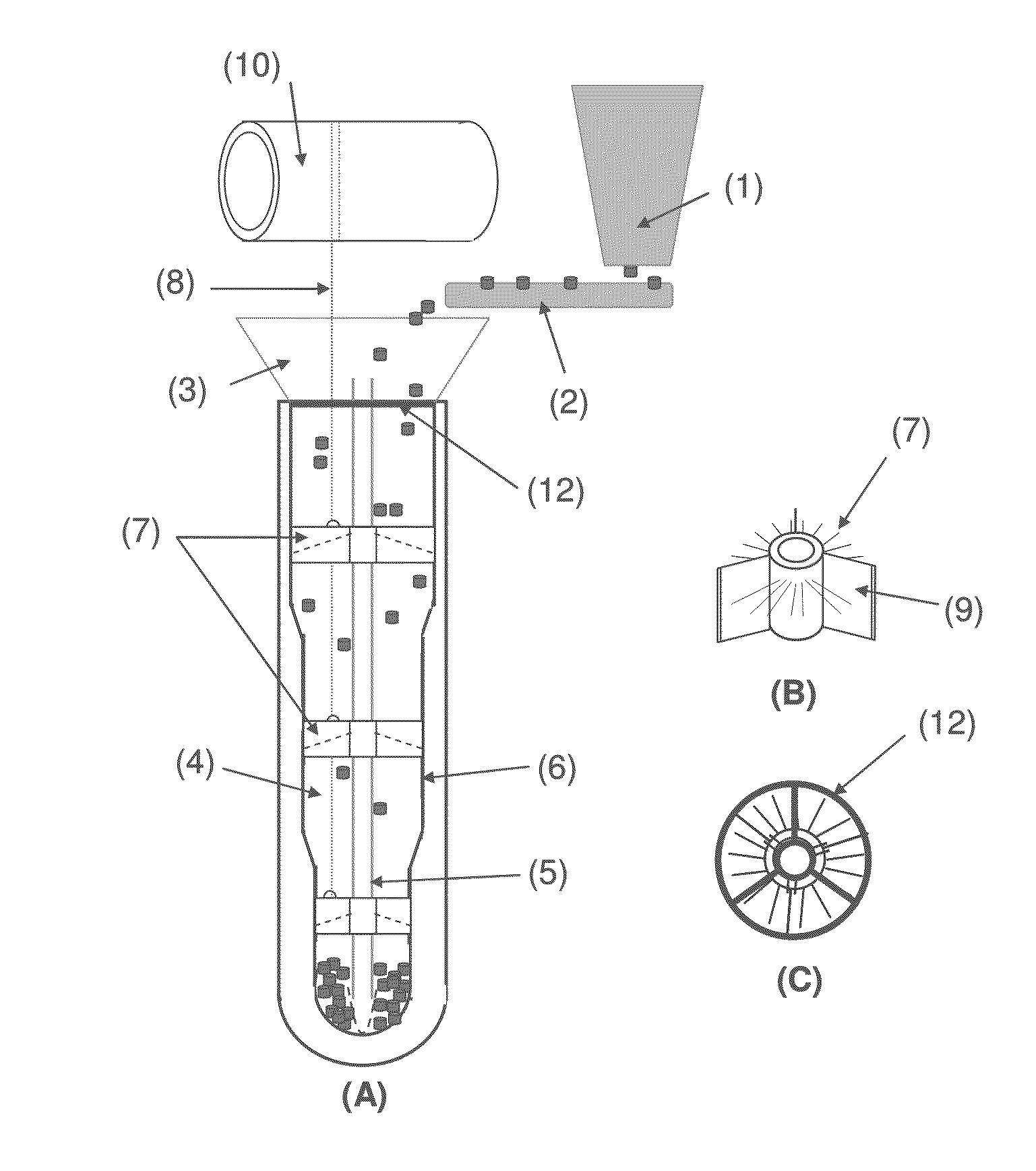
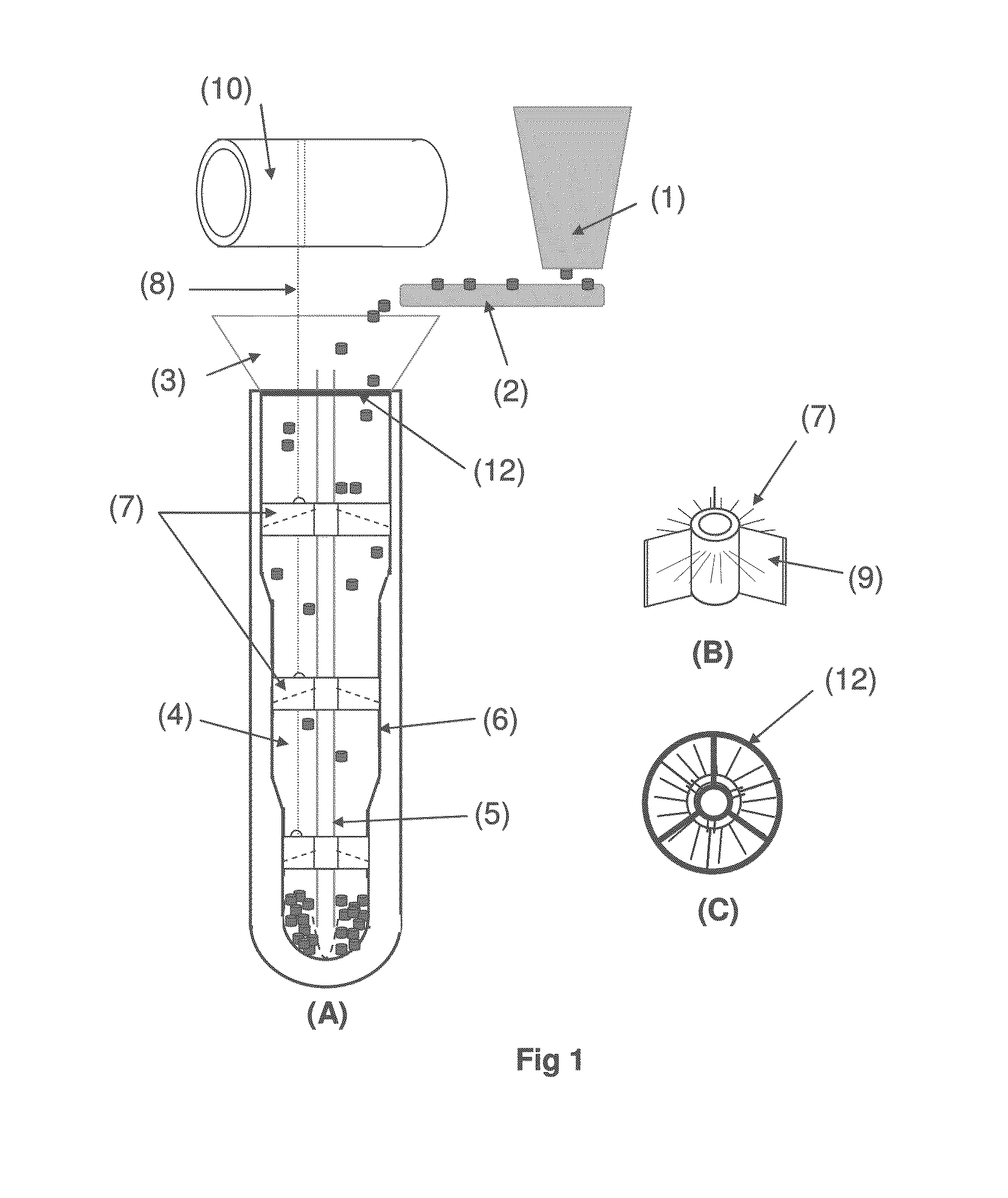
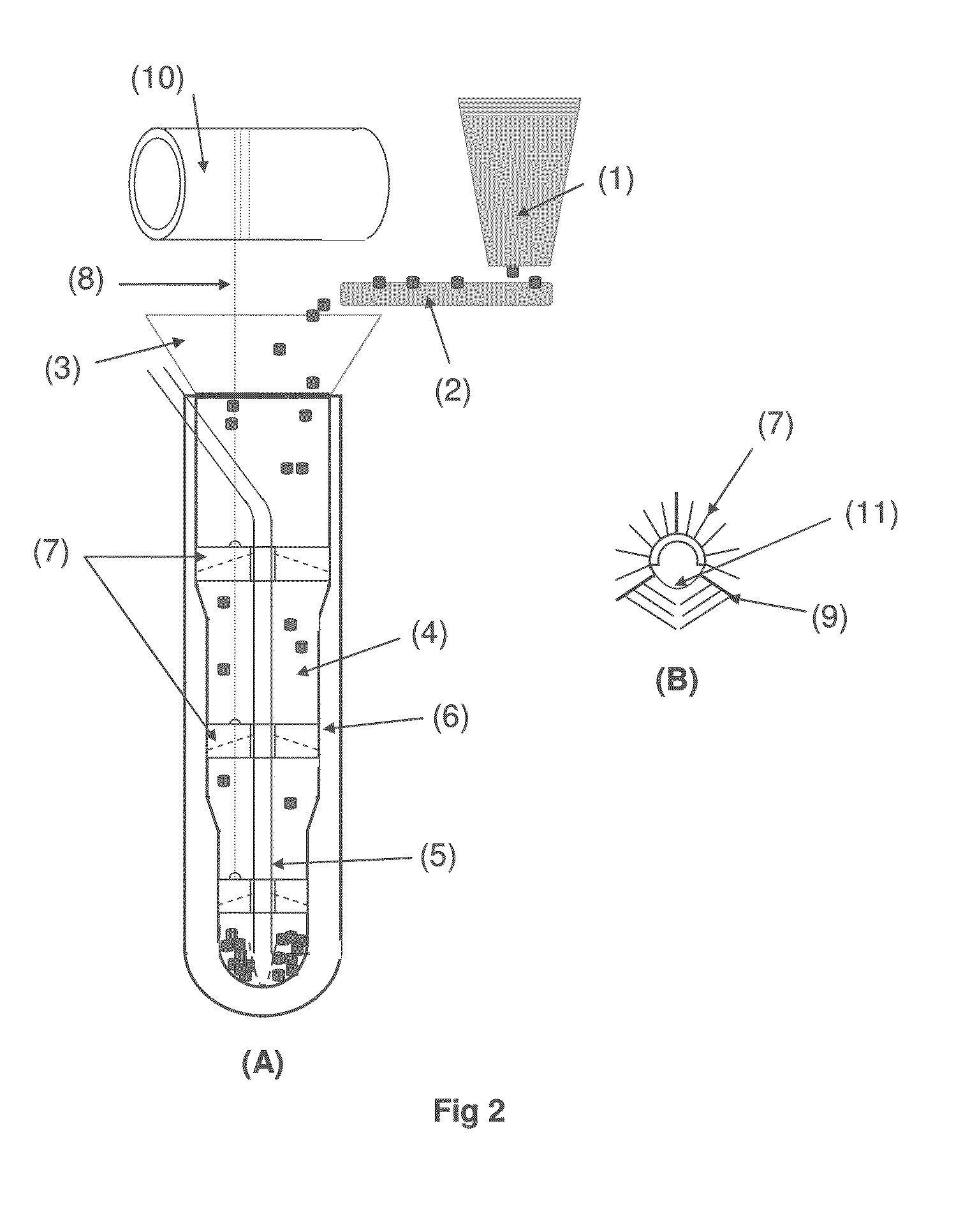
[0050]The present invention can be defined as a device for the dense loading of catalyst into the annular space 4 of bayonet tubes, each bayonet tube having a height in the range 10 m to 20 m, a diameter of the external tube 6 in the range 250 mm to 150 mm, and an external diameter of the internal tube 5 in the range 10 to 40 mm.

[0051]The annular space 4 containing the catalyst thus has a characteristic width of approximately 50 mm. In practice, depending on the case, the characteristic width of the annular space 4 can vary between 30 mm and 80 mm.

[0052]In addition, in some cases, the external tube 6 has a diameter which decreases from top to bottom in sections, which means that the characteristic width of the annular space 4 also reduces from top to bottom. The device of the invention is designed to adapt itself to these variations in characteristic width and retain its performance over the whole series of sections.

[0053]One of the major problems posed by catalytic particles being ...


PUM

PropertyMeasurementUnit
Material consumption rateaaaaaaaaaa
Lengthaaaaaaaaaa

Abstract

The present invention describes a device and a method for dense and homogeneous loading of catalyst into the annular space of bayonet tubes employed in a steam reforming reactor, said device employing removable slowing elements.

Description

FIELD OF THE INVENTION[0001]The present invention relates to the field of loading catalytic tubes used in tubular reactors employing highly endothermic or highly exothermic reactions. Thus, the present invention is particularly suitable for a reactor for steam reforming natural gas or various hydrocarbon cuts with a view to producing the CO+H2 mixture known as synthesis gas.[0002]Two major families of steam reforming reactors can be distinguished:[0003]Reactors in which the heat is supplied by a series of burners located inside the reactor, and those in which the heat is supplied via a heat transfer fluid, generally combustion fumes, said combustion taking place outside the steam reforming reactor per se.[0004]Certain reactors of this latter type, which will hereinafter be denoted exchanger-reactors, employ simple tubes. Others use double-walled concentric tubes which are also known as bayonet tubes. A bayonet tube can be defined as an inner tube surrounded by an outer tube which is...

Claims


Application Information

Patent Timeline
IPC IPC(8): B01J8/00B01J8/06
CPCB01J8/003B01J2208/00778B01J8/06B01J8/002B01J2208/00752B01J8/00
Inventor SANZ, ELENABEAUMONT, ROBERTSVEZIA, DANIELBOYER, CHRISTOPHE
Owner INST FR DU PETROLE
Learn More