In-pavement directional LED luminaire

a directional led and luminaire technology, applied in the direction of signalling/lighting devices, land aids, constructions, etc., can solve the problems of low efficiency (percent), high power consumption, and inapplicability of conventional design, and achieve the effect of high efficiency

Inactive Publication Date: 2005-06-07
FARLIGHT
View PDF6 Cites 90 Cited by
  • Summary
  • Abstract
  • Description
  • Claims
  • Application Information

AI Technical Summary

Problems solved by technology

A number of disadvantages related to this design include high maintenance costs, specifically relating to relamping due to low bulb life-time (500 to 1,000 hours) and the inability of conventional optics to efficiently provide complicated spatial luminous intensity distribution, which results in very low efficiency (percents) and high power consumption.
This configuration is typically implemented for relative low intensity devices, but for high intensity LEDs, this conventional design is not practical because of space limitations and the small size of the window in in-pavement luminaires.
Additionally, it is well-known that clusters of LEDs typically have various thermal problems, thereby negatively impacting on the photometric parameters such as luminous flux and color change.
While one design consideration may be to combine the cluster design with the non-imaging optic for an application that requires high intensity light, this combination unfortunately requires an individual optical element for each LED.

Method used


Image

  • In-pavement directional LED luminaire
  • In-pavement directional LED luminaire
  • In-pavement directional LED luminaire

Examples


Embodiment Construction

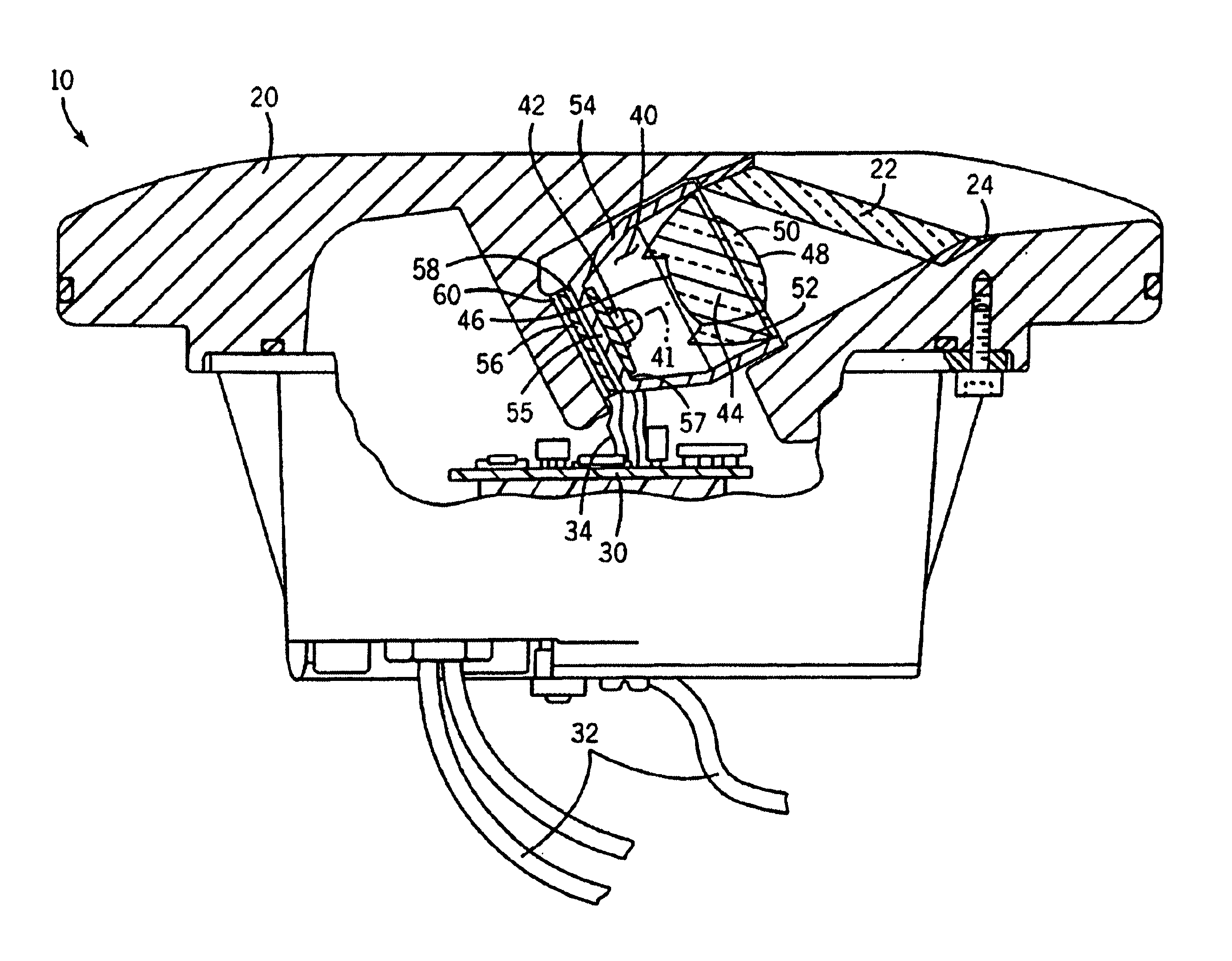
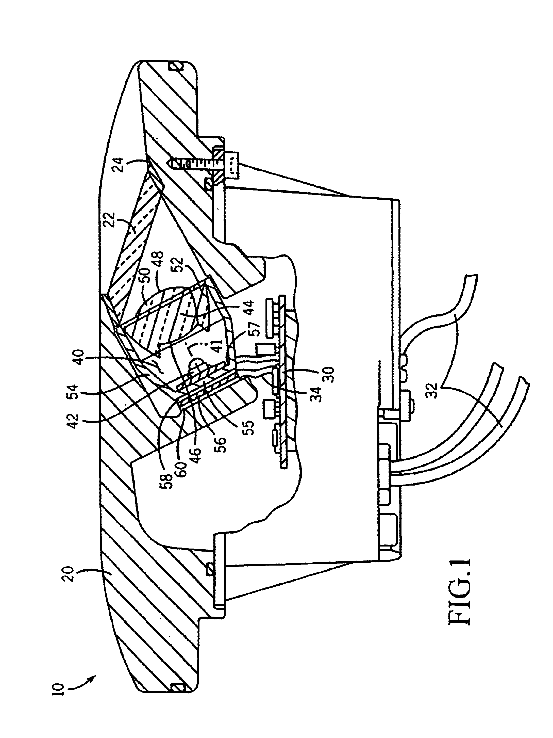
[0023]Referring now to FIG. 1, an in-pavement high intensity luminaire 10 includes a housing 20 having at least one transparent window 22 for output light passage and sealing member 24 forming a watertight seal between window 22 and housing 20.

[0024]A power controller input 32 is electronically connected to airport power infrastructure, and a power controller output 34 is electrically connected to a light module 40. Power controller input 32 and output 34 are designed to interface and operate with existing airport lighting infrastructure including intensity variation by constant current regulator compliance standard regulations.

[0025]Light module 40 includes a plurality of high flux LEDs 42, which are connected to power controller output 34 and located linearly with high density in a plane perpendicular to an optical axis 41 of LEDs 42. A non-imaging light transformer 44 includes an input end 46 facing LEDs 42, and an output end 48, located on an opposite end of transformer 44 from ...


PUM


Abstract

An in-pavement high intensity LED-based luminaire includes a housing, a power controller, a light module and a thermoelectric cooling device. The housing includes a generally flat top surface having at least one transparent window for output light passage. The power controller has an input and an output, wherein the input is electrically connected to an airfield power infrastructure and the output is electrically connected to a light module. The light module includes multiple high flux LEDs and a non-imaging light transformer. The non-imaging light transformer includes an input end opposite an output end, a refractive member located around the LED optical axis, and a total internal reflection member. The thermoelectric cooling device provides LED temperature control for emitted luminous flux, color and spatial intensity distribution stabilization, and is electrically connected to the power controller.

Description

CROSS-REFERENCE TO RELATED APPLICATIONS[0001]This application is a continuation-in-part application of U.S. Ser. No. 09 / 867,881 filed May 30, 2001 abandoned and U.S. Ser. No. 10 / 277,230 filed Oct. 21, 2002.BACKGROUND OF THE INVENTION[0002]1. Field of the Invention[0003]The present invention relates generally to luminaires for airfield lighting. In particular, the present invention relates to in-pavement directional luminaires for runways and taxiways including centerline, touchdown zone, threshold / end, edge, stop bar and the like.[0004]2. Discussion of the Related Art[0005]Although many specific improvements have been implemented in in-pavement luminaire designs, these basic improvements remain unchanged in that they generally consist of using an incandescent bulb as a light source combined with conventional optics as a beam forming element.[0006]A number of disadvantages related to this design include high maintenance costs, specifically relating to relamping due to low bulb life-t...

Claims


Application Information

Patent Timeline
Patent Type & Authority Patents(United States)
IPC IPC(8): E01F9/00F21V29/00F21S8/00F21V13/00F21V13/04B64F1/20F21V5/00F21V5/04F21V7/00F21V31/00H05B
CPCB64F1/20B64F1/205F21V5/04F21V29/74F21V29/004F21V17/02F21V7/0091B64C2027/8236F21V5/002F21V31/00F21W2111/06F21Y2101/02G02B19/0028G02B19/0061F21Y2115/10B64D2203/00F21V29/70
Inventor RIZKIN, ALEXANDERTUDHOPE, ROBERT H
Owner FARLIGHT
Why Eureka
Try Eureka