
Turnbuckle linkage assembly

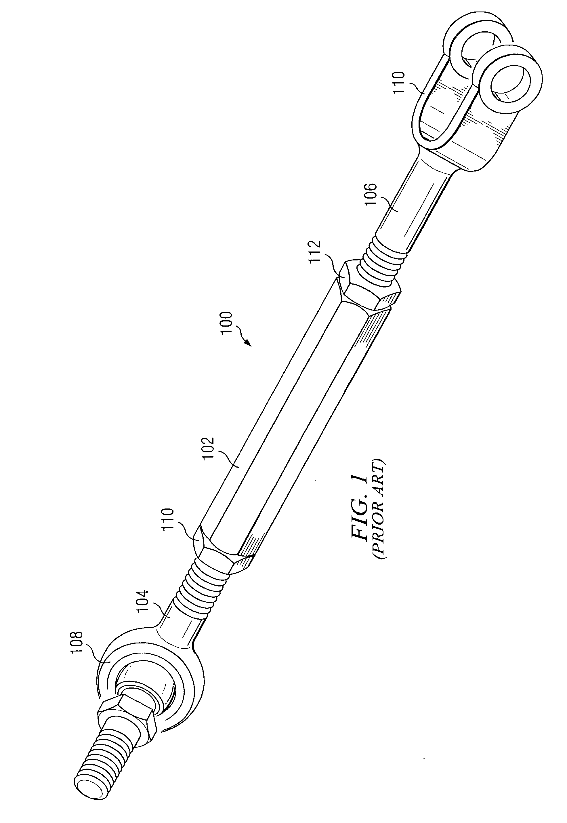
a technology of turnbuckle and linkage, which is applied in the direction of rod connection, mechanical control devices, instruments, etc., can solve the problems of not working at all, inconvenient or awkward, and inefficient or badly worked,

Inactive Publication Date: 2005-06-07
MIDWEST CONTROL PROD
View PDF5 Cites 35 Cited by
  • Summary
  • Abstract
  • Description
  • Claims
  • Application Information

AI Technical Summary

Benefits of technology

[0015]In another aspect of the invention, one of the first and second links is a control element while the other of the first and second links is an end connector that has a link portion for connecting to the turnbuckle and a machine portion for connecting to the machine. The first threaded connection defines a first end connecting to a second end, while the second connection defines a third end connecting to a fourth end. A bore is defined by the fourth end, and the third end is affixed in the bore. The interference fit is formed within the bore so as to permit rotation of the third end within the bore while preventing substantial axial translation of the third end.

Problems solved by technology

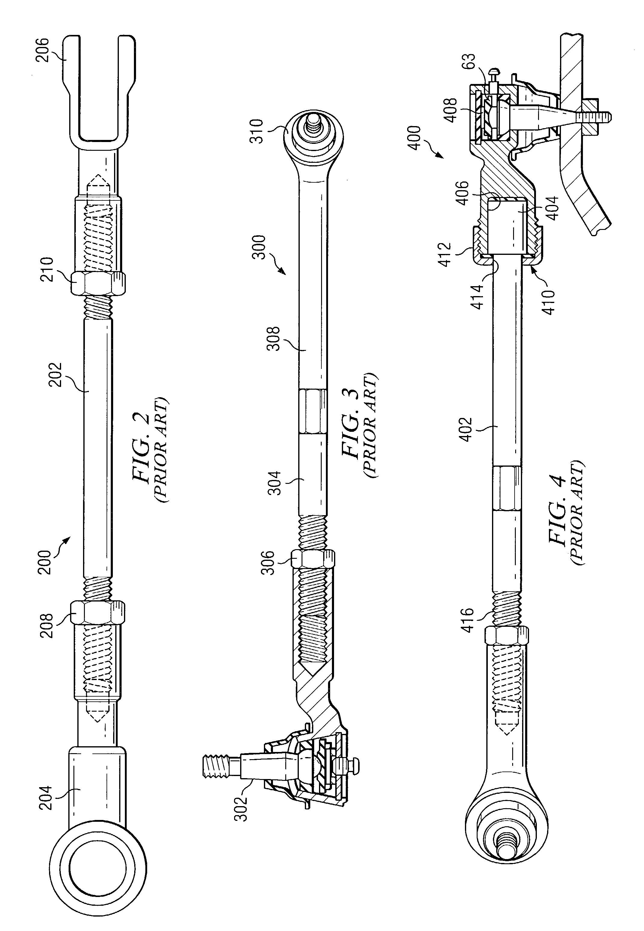
If the linkage assembly is too long or too short, it may work inefficiently or badly, may not work at all, or it may require an uncomfortable or awkward amount of pressure or “feel” on linkage systems that are manipulated by hand or foot.
This makes the adjustment procedure awkward and time consuming.
This is disadvantageous because depending on the position of the linkage assembly 400 in a machine, it may be extremely difficult to adjust the length of the assembly on just one end where structure of the machine is in the way of adjustment tools.
In addition, this configuration also has the risk of the cover nut 410 loosening, which would then permit the rod 404 to move axially, changing the length of the linkage assembly 400.

Method used


Image

  • Turnbuckle linkage assembly
  • Turnbuckle linkage assembly
  • Turnbuckle linkage assembly

Examples


Embodiment Construction

[0045]Referring to FIGS. 5A–B, a turnbuckle linkage assembly 10 has an elongated control element 12 with two ends 12a and 12b (as shown in FIG. 9) each threaded to a turnbuckle 14 (one shown in FIG. 5A). The control element 12 can be any structure such as an elongated solid rod, pipe, tube or push-pull cable. The turnbuckle 14 is rotatably attached to an end connector 16.

[0046]The end connector 16 has a link portion 18 for linking to the turnbuckle 14, and has a machine portion 20 for connecting to whatever machine it is a part of. The machine portion 20 is appropriately configured to impart a force with a particular strength and direction from the machine portion 20 to the link portion 18, or vice versa, and ultimately from one location 7 to another location 9 (shown on FIG. 9) in a machine. Thus, the machine portion 20 may have a clevis (or yoke), eye, ball joint, spherical rod end, or any other configuration to connect to mechanisms for manual shift levers, steering mechanisms, g...


PUM


Abstract

A turnbuckle linkage assembly is provided for transmitting a force between first and second locations in a machine. The assembly includes a first link for connecting to the first location such as a rod, tube or cable, a second link for connecting to the second location, and a turnbuckle. A first, threaded connection connects the turnbuckle to the first link, and a second connection connects the turnbuckle to the second link. The second connection and the second link are arranged along an axis, and an interference fit at the second connection is formed by the turnbuckle and the second link permitting the turnbuckle to rotate relative to the second link but axially affixing the turnbuckle to the second link.

Description

TECHNICAL FIELD[0001]The invention relates generally to mechanical linkage assemblies such as control or tie rods or cables that transfer motion from one location in a machine to another location in the machine, and more particularly, to linkages where adjusting the total length of the linkage assembly requires rotation of a connector on the assembly.BACKGROUND OF THE INVENTION[0002]Many different machines and vehicles use either rigid linkage assemblies, such as control rods and tubes, or flexible linkage assemblies, such as push-pull control cables. Rigid linkages are typically used to attach manual shifters on vehicles (such as in automobiles, trucks or maintenance and construction vehicles) to the mechanism that is being shifted or moved (e.g. to gears, brakes, hydraulic valves, steering systems or control arms for moving scoops, hoes, plows, etc.). Other linkage assemblies are used on non-vehicular machines such as medical equipment and packing machinery.[0003]The linkage assem...

Claims


Application Information

Patent Timeline
IPC IPC(8): F16B7/06F16B7/00F16C7/02F16C11/06
CPCF16C7/02F16C11/0623F16B7/06Y10T74/2151Y10T403/5706Y10T403/32221Y10T403/32213Y10T403/29Y10T403/32065F16C7/06
Inventor RAUSCHERT, MARK C.
Owner MIDWEST CONTROL PROD
Learn More