
Coupling device of a motor vehicle

a technology of coupling device and motor vehicle, which is applied in the direction of rotary clutches, fluid couplings, brake systems, etc., can solve the problems of low precision of clutch actuation effected through play-afflicted bearings, unfavorable higher pressure on the clutch pedal at the clutch pedal, and impair the function of the clutch pedal, so as to reduce the production cost of the whole control mechanism, improve the mechanical properties, and improve the effect of mechanical properties

Inactive Publication Date: 2009-08-11
ZF FRIEDRICHSHAFEN AG
View PDF13 Cites 1 Cited by
  • Summary
  • Abstract
  • Description
  • Claims
  • Application Information

AI Technical Summary

Benefits of technology

The invention is about a coupling device for a motor vehicle that includes a clutch and a servo-assisted control mechanism. The clutch is designed as a pressing spring and a clutch release sleeve, and the control mechanism includes a primary drive and several slave cylinders. The servo drive has several pneumatic actuators and the primary drive can be a hydraulic adjusting drive or a mechanical adjusting drive. The control valve of the servo drive can be a hydraulically controllable proportional valve or an electrically controllable magnetic-proportional valve. The invention allows for improved operational reliability and reduced installation space and production costs.

Problems solved by technology

Disadvantageous to it is, in addition, to the relatively large installation space requirement also a low precision of the clutch actuation effected through play-afflicted bearings, joints and guidances.
The beneficial force-displacement translation of leverage is, however, thereby canceled, which with the clutch actuation leads unfavorably to higher pressure on the pedal at the clutch pedal.
With the ring-shaped central shifter, it also involves an expensive special subassembly through the arrangement of which, in addition with a leakage escaping hydraulic means, can fall on the friction surfaces of the clutch and consequently can impair their functions.
However, it is disadvantageous to this well known coupling device that the central shifter is constructed in a complicated manner and is thus relatively expensive to produce, and that with a leakage escaping hydraulic means in the hydraulic actuator of the primary drive, as well as with a simple hydraulic control mechanism, provided with a centrally arranged slave cylinder it can impair the function of the clutch.

Method used


Image

  • Coupling device of a motor vehicle
  • Coupling device of a motor vehicle
  • Coupling device of a motor vehicle

Examples


Embodiment Construction

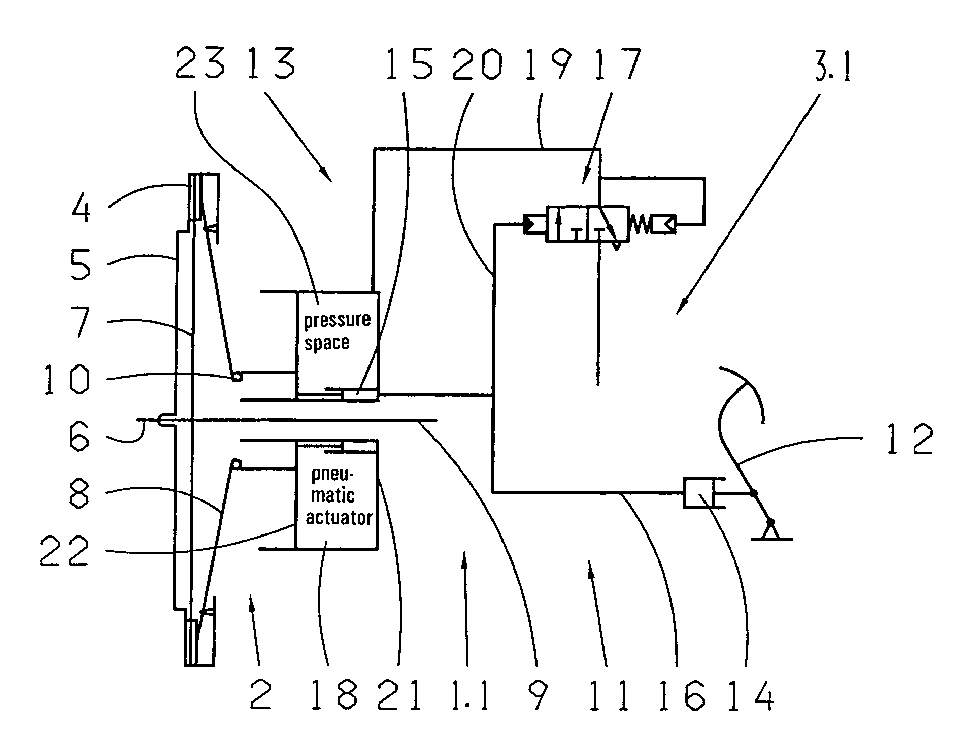
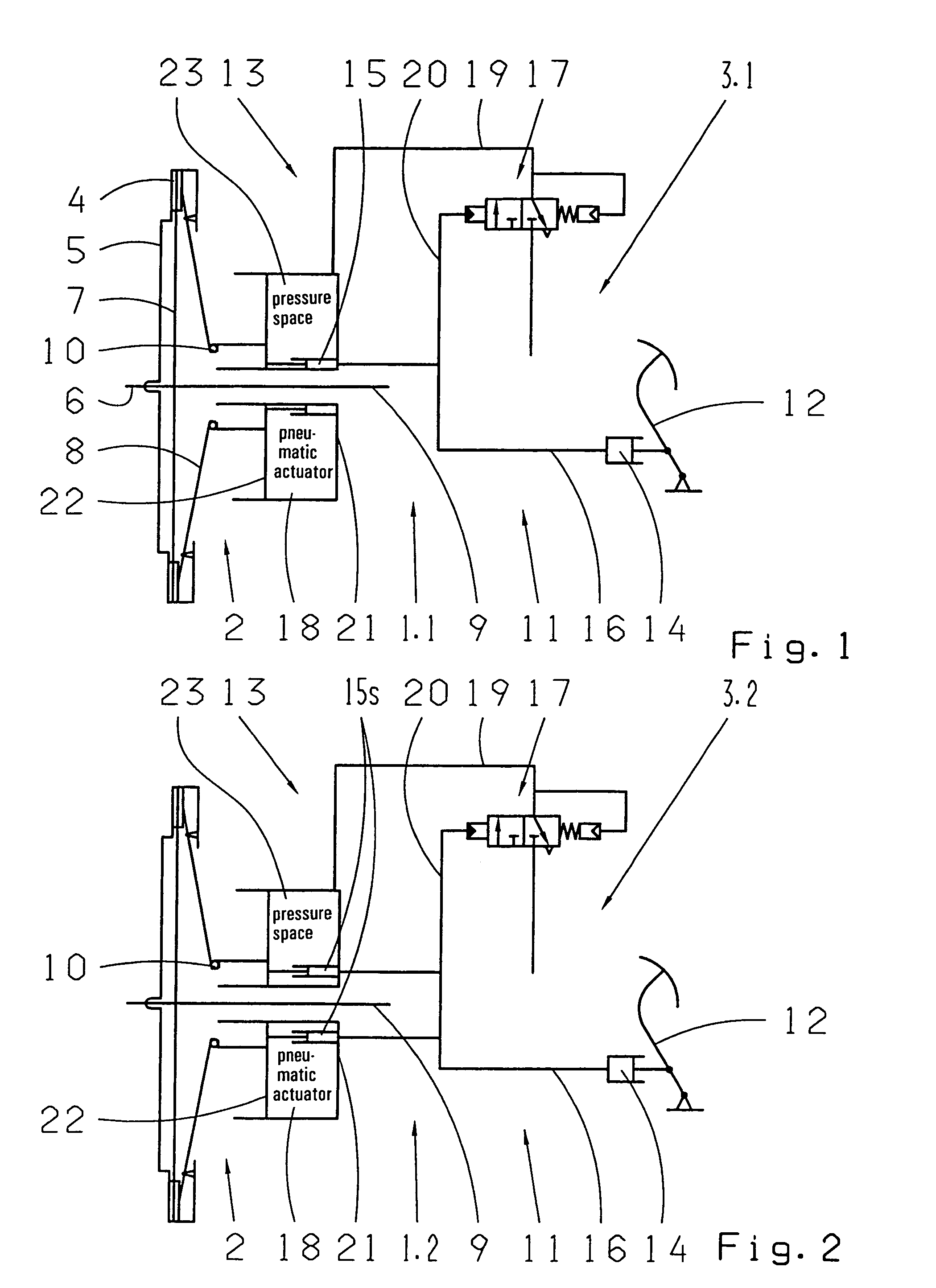
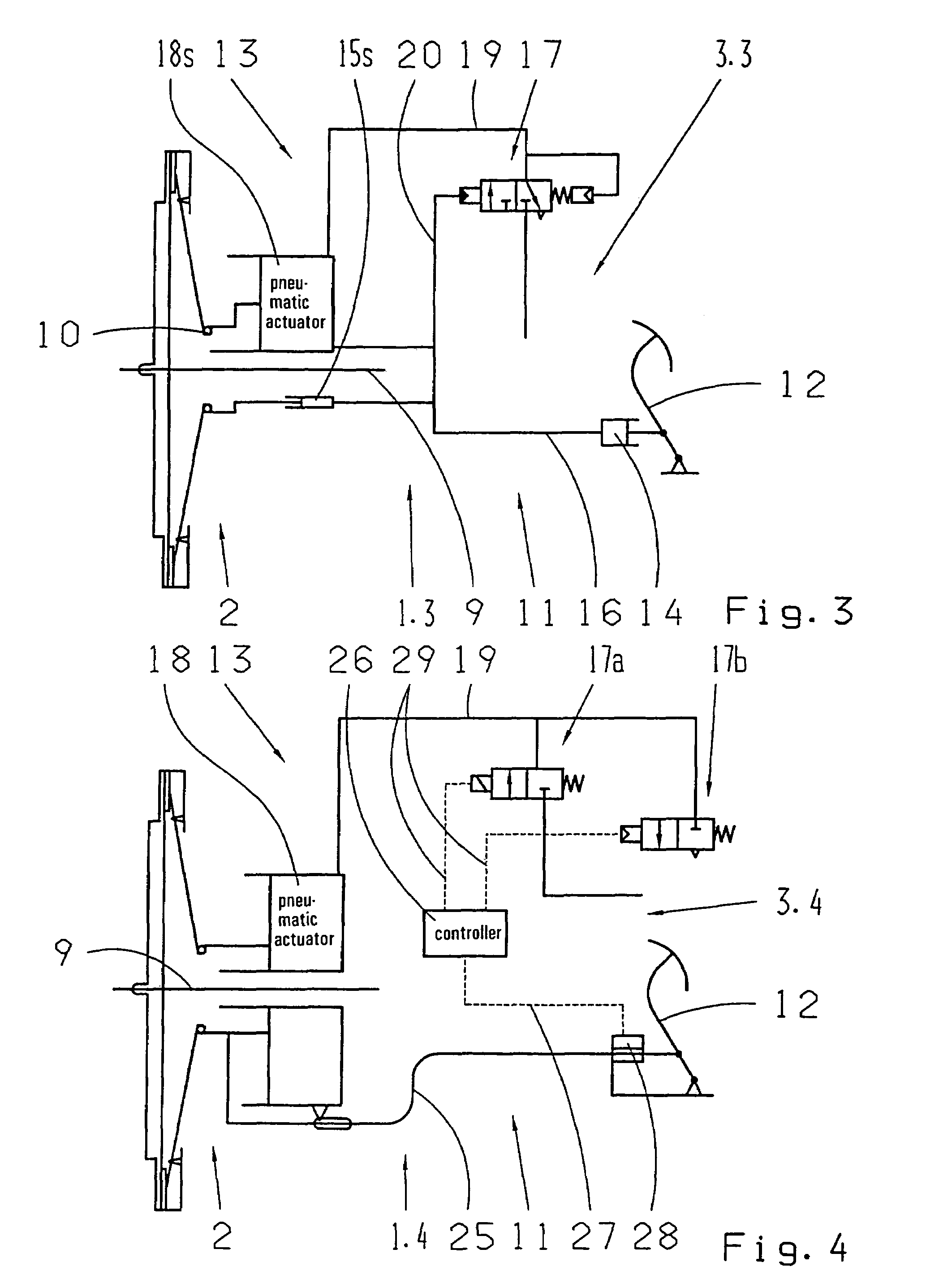
[0033]According to FIG. 1, a coupling device 1.1 shows a clutch 2 and a dedicated control mechanism 3.1. The clutch 2 is designed as an insertion-dry-clutch and, in an actually well-known way, includes a pressure plate 4, which is connected on the input side, via a fly wheel 5, to a crank shaft 6 of an internal combustion engine (not depicted in more detail), a driver disk 7, a pressing spring 8 loaded in inoperative condition, attached by one to the pressure plate 4 and designed as a diaphragm spring, is built in between the pressure plate 4 and the fly wheel 5 and is connected torque proof to an input shaft 9 of a transmission (not depicted in more detail). The clutch 2 is disengageable by an axial displacement of a clutch release sleeve 10 ordered to the pressing spring 8 in the direction of the internal combustion engine and reinsertable in the opposite direction by a subsequent axial displacement.

[0034]The control mechanism 3.1 is servo-assisted and thus, in addition, to a prim...


PUM


Abstract

A coupling device of a motor vehicle with a clutch arranged in the force flow between a drive motor and a transmission and a dedicated servo-assisted control mechanism. The clutch is designed by way of a pressing spring as a passively lockable and via a clutch release sleeve disengageable and insertable dry friction coupling and the control mechanism includes an operative primary drive between a clutch pedal and the clutch release sleeve and a pneumatically operative servo drive with a pneumatic actuator ordered immediately to the clutch release sleeve and with a control valve controllable by the clutch pedal.

Description

[0001]This application claims priority from German Application Serial No. 10 2005 047 930.8 filed Oct. 6, 2005.FIELD OF THE INVENTION[0002]The invention concerns a coupling device of a motor vehicle with a clutch arranged in the force flow between a drive motor and a transmission and a dedicated servo-assisted control mechanism, wherein the clutch is designed by way of a pressing spring as a passively lockable and, via a clutch release sleeve, disengageable and insertable dry friction coupling, and wherein the control mechanism includes an operative primary drive between a clutch pedal and the clutch release sleeve as well as a pneumatically operative servo drive with a pneumatic actuator ordered immediately to the clutch release sleeve and with a control valve controllable by the clutch pedal.[0003]A clutch arranged in the drive chain of a motor vehicle between a drive motor, designed generally as an internal combustion engine, and a transmission serves essentially as the transmiss...

Claims


Application Information

Patent Timeline
Patent Type & Authority Patents(United States)
IPC IPC(8): F16D25/08
CPCF16D48/04F16D25/088F16D48/02F16D2048/0212F16D2048/0221F16D2500/1028F16D2500/1045F16D2500/3023F16D2500/3026F16D2500/31413
Inventor BADER, JOSEFRENNER, STEFAN
Owner ZF FRIEDRICHSHAFEN AG
Learn More