
Control system for positioning at least two floating wind turbines in a wind farm

a technology of control system and wind farm, which is applied in the direction of machines/engines, vessels, transportation and packaging, etc., can solve the problems of increasing the load of a downstream floating wind turbine, reducing the overall power production of the wind farm, and reducing power

Pending Publication Date: 2022-09-08
SIEMENS GAMESA RENEWABLE ENERGY AS
View PDF37 Cites 2 Cited by
  • Summary
  • Abstract
  • Description
  • Claims
  • Application Information

AI Technical Summary

Benefits of technology

The patent describes a new way to increase the amount of wind energy produced from a wind farm while reducing fatigue loads on the structure. This is achieved by using a floating wind turbine that can actively move to avoid or minimize the impact of wind on other turbines in the farm. This reduces the energy lost by wind turbines due to wake problems, resulting in higher production of energy and lower costs.

Problems solved by technology

These phenomena result in a decrease of an overall power production of the wind farm and an increase of a load for a downstream floating wind turbine.
The decrease of power may be a direct result of the lower wind speed, while the increase in the load is a consequence of the turbulences causing vibrations in a mechanical loading of the downstream floating wind turbine.
Particularly because the location comprising the minimum wake influence must not be the location comprising an acceptable or even a good power production and / or the location where the two floating wind turbines are exposed to minimum or not harmful loads.
Taking into account an incoming boat may provide the possibility that even if a boat is entering the wind farm which should in a first step be inhibited, a harmful damage of the two floating wind turbines or the boat and thereby personal risk may effectively be inhibited.
This would potentially increase an annular energy production of the wind farm and may decrease a loading of the floating wind turbine.

Method used


Image

  • Control system for positioning at least two floating wind turbines in a wind farm
  • Control system for positioning at least two floating wind turbines in a wind farm
  • Control system for positioning at least two floating wind turbines in a wind farm

Examples


Embodiment Construction

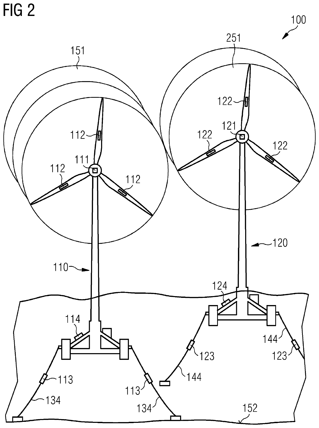
[0097]The illustration in the drawings is schematic. It is noted that in different figures, similar or identical elements or features are provided with the same reference signs or with reference signs, which are different from the corresponding reference signs only within the first digit. In order to avoid unnecessary repetitions elements or features which have already been elucidated with respect to a previously described embodiment are not elucidated again at a later position of the description.

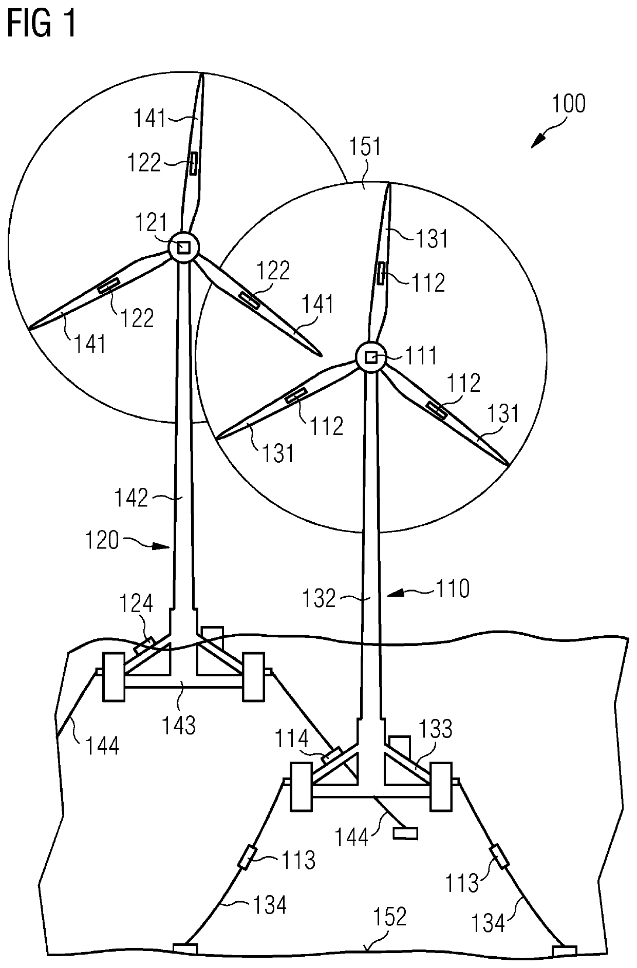
[0098]FIG. 1 shows a wind farm 100 comprising a second floating wind turbine 120 operating inside a wake property 151 of a first floating wind turbine 110 according to another exemplary embodiment of the invention.

[0099]The first floating wind turbine 110 comprises a first floating foundation 133, a first tower 132 mounted to the first floating foundation 133, and three first blades 131 each mounted via a hub and nacelle to the first tower 132. The first floating wind turbine 110 is held in...


PUM


Abstract

A control system for positioning at least two floating wind turbines in a wind farm is provided. The control system includes a measuring device configured for measuring an incoming wind field at the two wind turbines, a determining device, wherein the determining device is configured for determining a wake property at the two wind turbines, wherein the determining device is configured for determining a propagation path of the wake property through the wind farm based on the determined wake property at the at least two floating wind turbines, wherein the determining device is configured for determining a location for each of the at least two floating wind turbines including a minimized wake influence based on the determined propagation path of the wake property through the wind farm, and a repositioning device configured for repositioning each of the at least two floating wind turbines to the determined location.

Description

CROSS-REFERENCE TO RELATED APPLICATIONS[0001]This application claims priority to PCT Application No. PCT / EP2020 / 069955, having a filing date of Jul. 15, 2020 which claims priority to EP Application No. 19193197.1, having a filing date of Aug. 22, 2019, the entire contents both of which are hereby incorporated by reference.FIELD OF TECHNOLOGY[0002]The following relates to a control system for positioning at least two floating wind turbines in a wind farm. Further, the following relates to a wind farm and a method for positioning at least two floating wind turbines in a wind farm.BACKGROUND[0003]In the technical field of floating wind turbines, it is known to install a plurality of floating wind turbines in a floating wind farm. Floating wind turbines installed in the wind farm interact with each other thought their wakes. The wake of a floating wind turbine is produced because the floating wind turbine extracts energy out of an incoming wind flow. Wake causes a reduced wind speed, al...

Claims


Application Information

Patent Timeline
Patent Type & Authority Applications(United States)
IPC IPC(8): F03D13/25B63B21/50F03D7/02F03D7/04F03D9/25
CPCF03D13/25B63B21/50F03D7/0224F03D7/048F03D9/25F05B2240/93B63B2035/446F05B2270/204F05B2270/20F05B2270/8042F03D7/0202F03D7/049
Inventor ESBENSEN, THOMASHOEGH, GUSTAVLAUGESEN, KASPER
Owner SIEMENS GAMESA RENEWABLE ENERGY AS
Learn More