

Outboard motor and tiller handle thereof
- Summary
- Abstract
- Description
- Claims
- Application Information
AI Technical Summary
Benefits of technology
Problems solved by technology
Method used
Image

Examples
Embodiment Construction
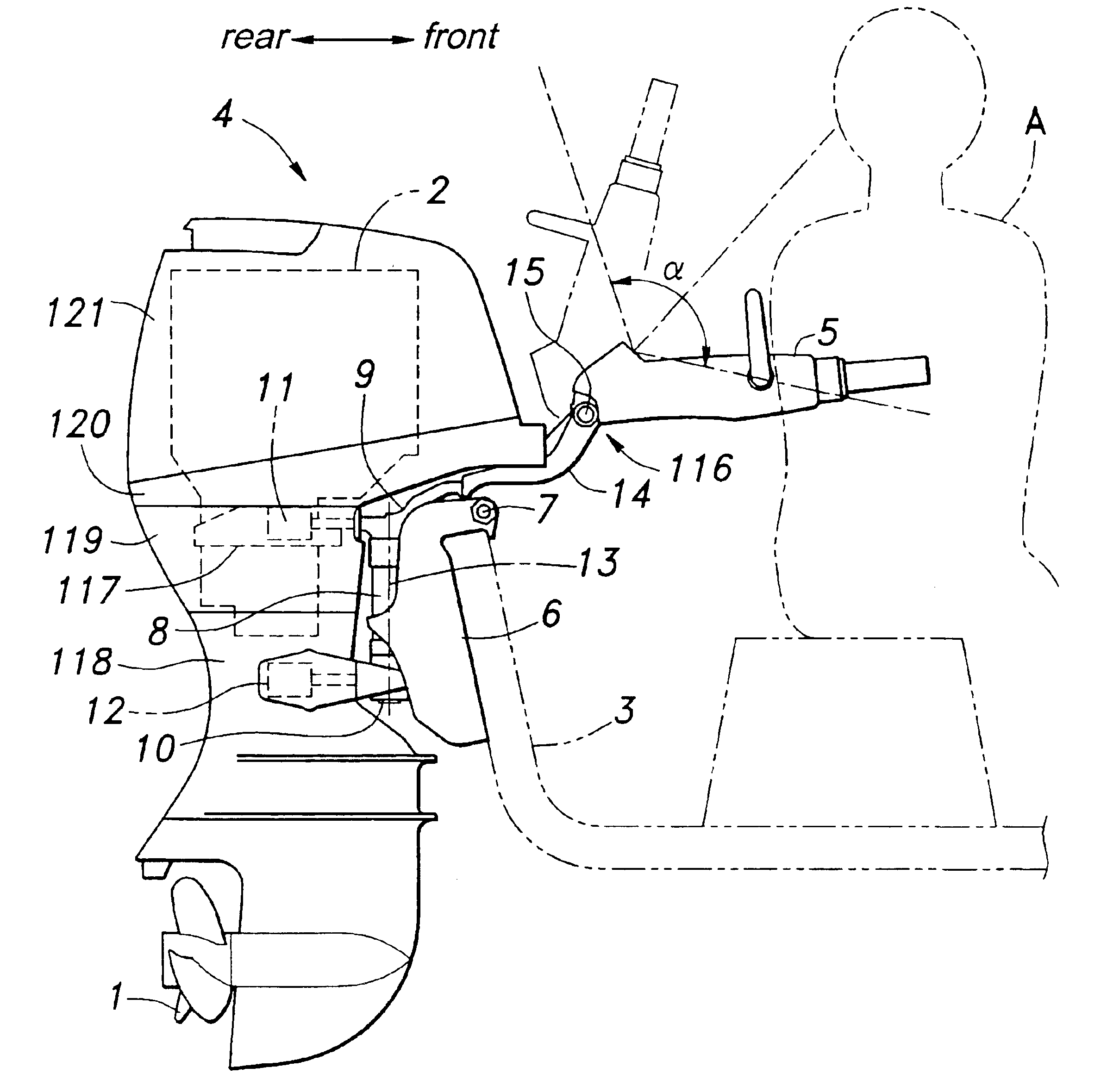
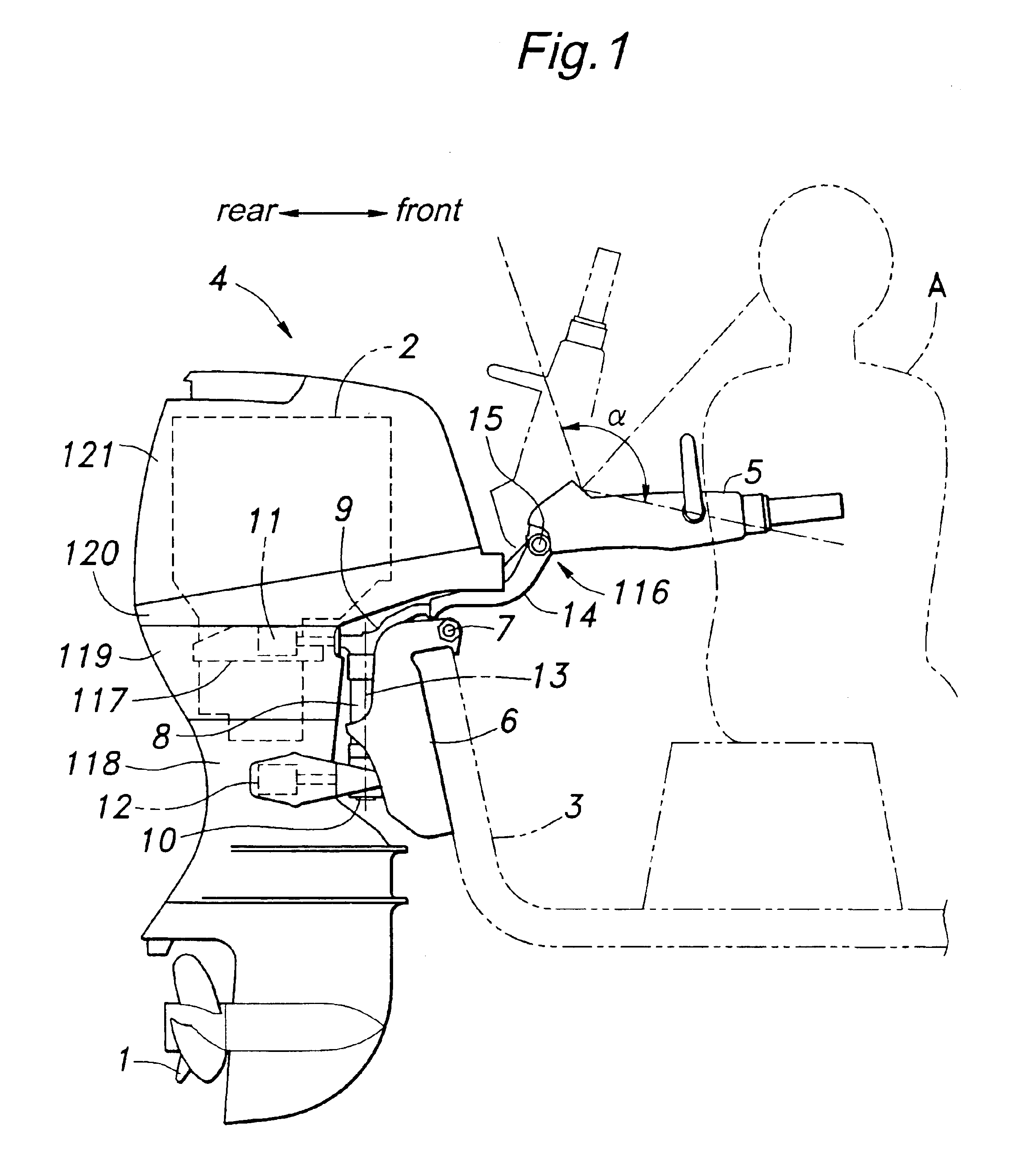
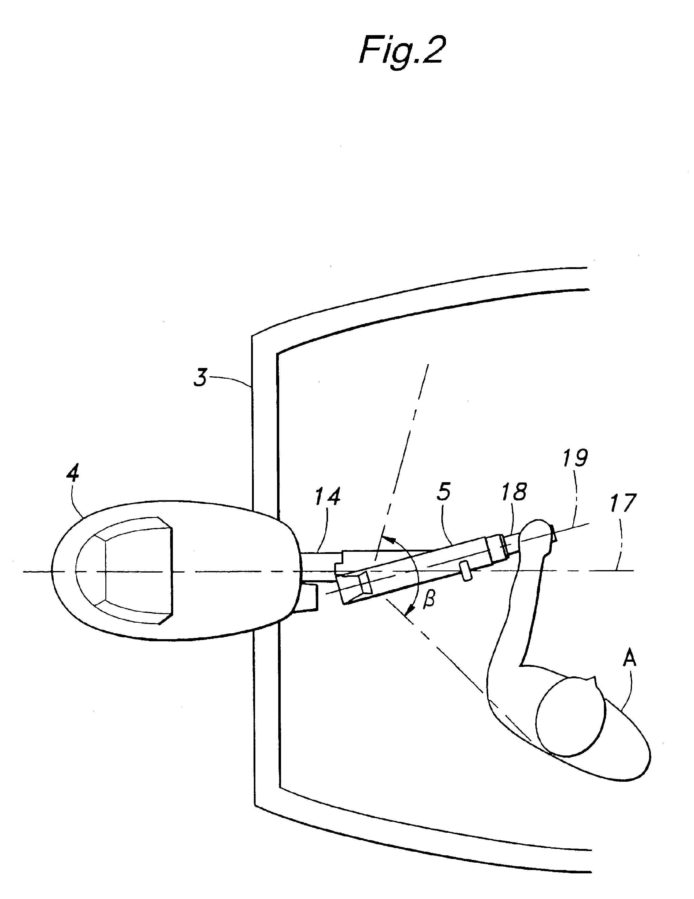
[0046]FIG. 1 is a side view for showing an overall structure of an outboard motor according to the present invention. This outboard motor comprises a propulsion propeller 1, an engine (power source) 2 for driving the propeller 1, a motor main body 4 steerably attached to a watercraft body 3 via an attachment bracket 6, and a tiller handle 5 extending toward the watercraft body 3 to steer the motor main body 4.
[0047]The attachment bracket 6 is coupled to a swivel case (a member on the attachment bracket) 8 so as to be pivotable around a lateral tilt shaft 7. The swivel case 8 comprises a cylindrical part for pivotally supporting a vertical swivel shaft, and a mount frame (a member on the motor main body) 9 is attached to an upper end of the swivel shaft while a lower mount housing 10 is attached to a lower end of the same. The mount frame 9 and the lower mount housing 10 are fastened to an engine mount case 117 and extension case 118 via oscillation dampers 11, 12 consisting of elast...
PUM
 Abstract
Description
Claims
Application Information