Electrolytic Ozone Generator with Membrane Electrode

a technology of electrolysis ozone and membrane electrodes, applied in the field of electrolysis ozone generators, can solve the problems of gas and source water leakage, aging of the seal, and the inability to seal, and achieve the effects of stable tightening force, stable function, and low ozone volume of the electrolysis ozone generator

Inactive Publication Date: 2012-05-31
HSU MINGYUNG
View PDF6 Cites 0 Cited by
  • Summary
  • Abstract
  • Description
  • Claims
  • Application Information

AI Technical Summary

Benefits of technology

[0011]The primary object of the present invention is to provide an electrolytic ozone generator with membrane electrode which has a simple structure, is cost-effective and provides a better seal effect to achieve mass production. After a period of operation, the electrolytic ozone generator still keeps an excellent seal so that the electrolytic ozone generator can generate ozone steadily.
[0024]Compared to the prior art, the present invention has the following effects.
[0027]3. The frame body and the fastening plate are tightly connected with the cathode structure through screws in a mechanical tightening way. The tightening plate provides a tightening force to the conductive column. Because the inner of the seal is smooth after deformed, the tightening force passes the flow field plate and the anode diffusion layer through the conductive column and is transmitted to the anode electrocataly layer and the proton exchange membrane, providing a stable tightening force as required. Besides, the conductive column is applied with a force and has a gap relative to the flow field plate, so the periphery and the outer side of the conductive column will be deformed. Through the thin body to bear deformation, the outer side of the thin body won't be influenced by the screws and the tightening plate. In this way, the deformation and airtightness of the seal won't have a change. Therefore, through the thin body, the pressure to deform the seal and the pressure for the anode electrocataly layer to tighten the proton exchange membrane are different and separate, so that the electrolytic ozone generator keeps a stable function.
[0028]4. After operation, the thickness of the anode electrocatalyst layer will gradually be thinned. When the thickness is thin, the fastening plate applies a fastening force to the conductive column and the conductive column is moved downward through the thin body so as to compensate for the lost pressure because the thickness of the anode electrocatalyst layer becomes thin. This can prevent the anode electrocatalys layer and the ion exchange layer from not having enough fastening force to lower the ozone volume of the electrolytic ozone generator.
[0029]5. The cathode fixed plate of the cathode structure of the present invention has screw holes which are used to fasten the electrolytic ozone generator with membrane electrode and connect with the cathode electrode of direct current, having the same function of a conventional cathode fixed plate. The cathode fixed plate of the present invention has the deflector grooves to receive source water. The source water and the gas product convect and diffuse in the grooves to have conductive and cooling functions as the conventional deflector plate. The cathode fixed plate of the present invention has the drainage hole to drain the water of cathode and the gas production. The cathode fixed plate of the present invention is made of a metallic titanium material to prevent corrosion, without the need of corrosion-resisting material and corrosion-resisting treatment. The cathode fixed plate has fastening, guide, cooling and drainage functions, combining the functions of a conventional cathode fixed plate, an anticorrosive plate, a frame and a deflector plate. Compared to the conventional ozone generator, the present invention is simple in technique, is convenient for assembly and lowers the cost about 20-30%.

Problems solved by technology

1. Ozone has a strong oxidized corrosion. During operation, the large-sized seal gets contact with ozone direct. The surface area is large, which is easy to be oxidized and corroded. After a period of time, the seal will be aging and its seal capability will lose to result in leakage of gas and source water.
2. There are many seals in the conventional ozone generator. This increases cost and the operation is complicated. No matter how small the ozone contact area is, the oxidization and corrosion cannot be avoided, so the seal may lose its efficacy.
3. After a long time, the seal made of silicon rubber is unable to resist ozone of high concentration and will harden to lose its resilience, without seal function.
4. After fastened, the fastening force provides two pressures to deform the seal and to the anode electrocataly layer for fastening the proton exchange membrane. The pressure to deform the seal and the pressure for the anode electrocataly layer to fasten the proton exchange membrane are different, which will cause the other pressure too large or too small. The seal capability and the anode electrocataly layer to fasten the proton exchange membrane are influenced, so the electrolytic ozone generator with membrane electrode is unstable and the volume of ozone may decrease.
5. After operation, the thickness of the anode electrocataly layer gradually thin, and the fastening plate cannot provide enough pressure and is unable to compensate for the lost pressure caused by the thin anode electrocataly layer, so the anode structure of the electrolytic ozone generator is loosened. The pressure to the anode electrocataly layer and the proton exchange membrane is not enough, so the volume of ozone generated by the electrolytic ozone generator with membrane electrode is decreased.
6. The conventional cathode structure comprises a cathode fixed plate, an anticorrosive plate, a frame, a deflector plate, a seal, an anode diffusion layer, a cathode electrocatalyst layer, which has too many parts. The production and assembly are complicated to influence its reliability and to increase cost.

Method used


Image

  • Electrolytic Ozone Generator with Membrane Electrode
  • Electrolytic Ozone Generator with Membrane Electrode
  • Electrolytic Ozone Generator with Membrane Electrode

Examples


Embodiment Construction

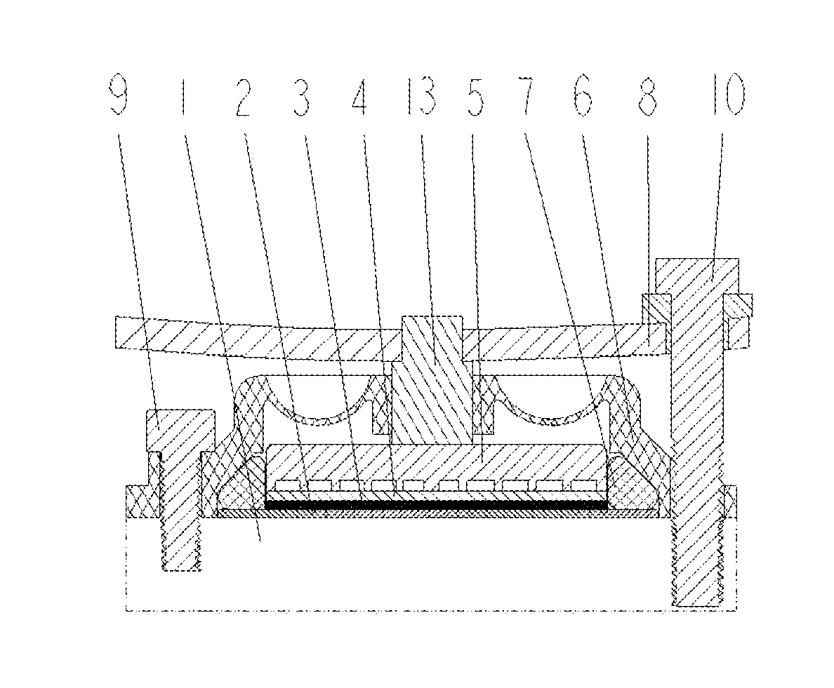
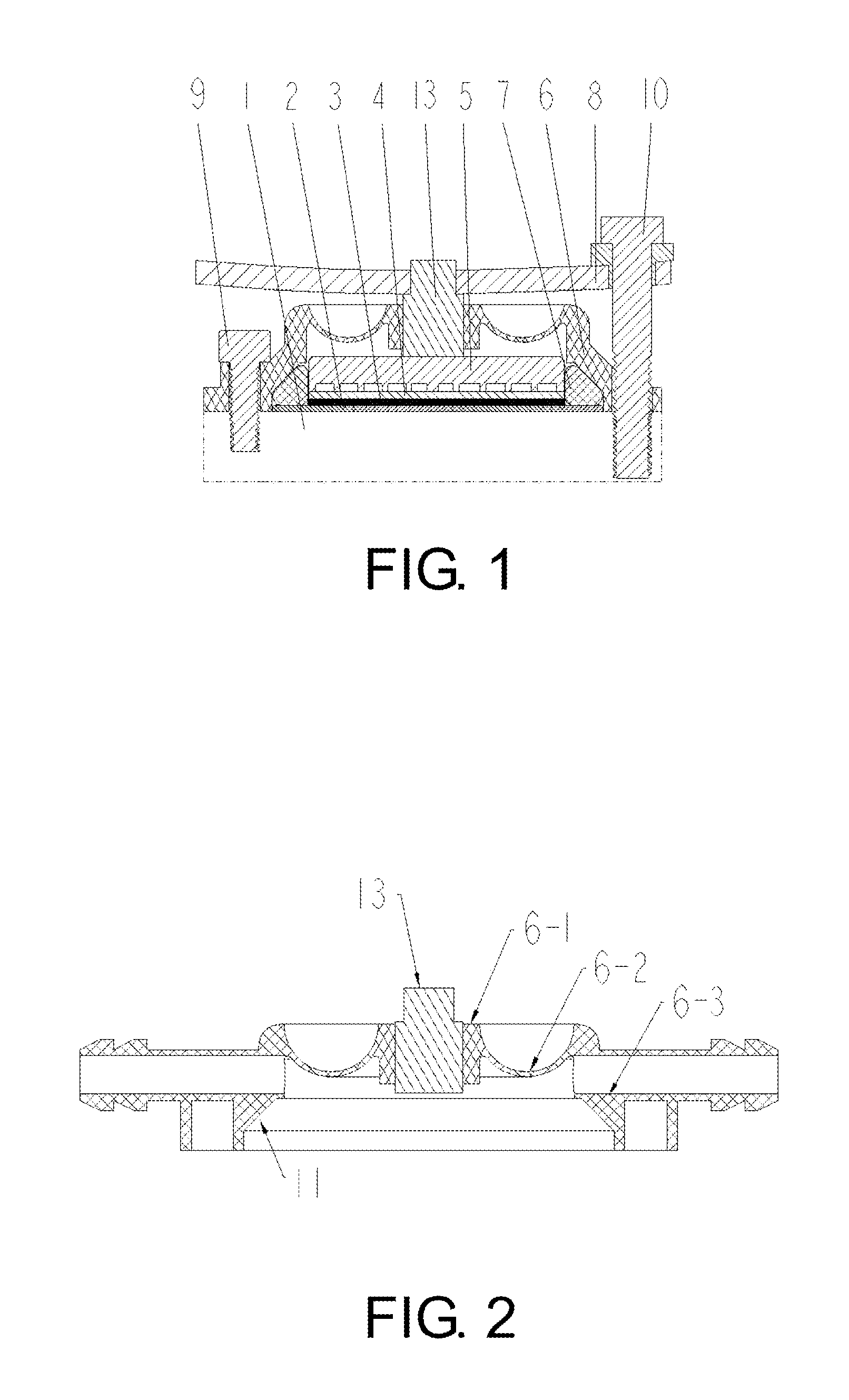
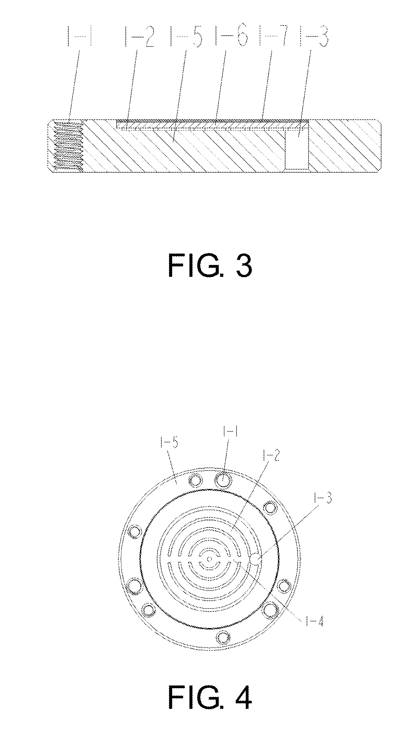
[0034]Embodiments of the present invention will now be described, by way of example only, with reference to the accompanying drawings.

[0035]As shown in FIG. 1 through FIG. 4, the electrolytic ozone generator with membrane electrode of the present invention comprises a cathode structure 1. The cathode structure 1 comprises a cathode fixed plate 1-5 which is made of a metallic titanium material. The cathode fixed plate 1-5 has a plurality of screw holes 1-1 which are evenly arranged around a circumferential portion of the cathode fixed plate 1-5. The cathode fixed plate 1-5 further has annular deflector grooves 1-2 and a transverse groove 1-4 which passes through the central portions of the annular deflector grooves 1-2. The annular deflector grooves 1-2 are interconnected through the groove 1-4 and communicate with a drainage hole 1-3. A cathode diffusion layer 1-6 is provided on the cathode fixed plate 1-5. A cathode electrocatalyst layer 1-7 is provided on the cathode diffusion lay...


PUM

PropertyMeasurementUnit
thicknessaaaaaaaaaa
pore diameteraaaaaaaaaa
conductiveaaaaaaaaaa

Abstract

An electrolytic ozone generator with membrane electrode includes a proton exchange membrane (2), an anode electrocatalyst layer (3), an anode diffusion layer (4), a flow field plate (5), a cathode structure (1) and a frame body (6). The frame boy (6) has a frame sealing groove (11) therein. A seal (7) is provided in the frame sealing groove (11). The frame body (6) is tightly connected with the cathode structure (1) through screws (9) so that the seal (7) is to seal the proton exchange membrane (2), the anode electrocatalyst layer (3) and the frame body (6) completely and tightly. The present invention has a simple structure, is cost-effective and provides a better seal effect to achieve mass production. After a period of operation, the electrolytic ozone generator still keeps an excellent seal, so that the electrolytic ozone generator can generate ozone steadily.

Description

BACKGROUND OF THE INVENTION[0001]1. Field of the Invention[0002]The present invention relates to an electrolytic ozone generator, and more particularly to an electrolytic ozone generator with membrane electrode with pure water as raw material.[0003]2. Description of the Prior Art[0004]There are many electrolytic ozone generators on the market, such as Chinese Utility Model Patent No. ZL200520113829.9 titled “anode structure of electrolytic ozone generator” and Chinese Patent Application No. 97122126.X titled “electrolytic ozone generator”. The aforesaid structures have the following shortcomings.[0005]1. Ozone has a strong oxidized corrosion. During operation, the large-sized seal gets contact with ozone direct. The surface area is large, which is easy to be oxidized and corroded. After a period of time, the seal will be aging and its seal capability will lose to result in leakage of gas and source water.[0006]2. There are many seals in the conventional ozone generator. This increas...

Claims


Application Information

Patent Timeline
Patent Type & Authority Applications(United States)
IPC IPC(8): C25B9/10C25B9/23
CPCC25B9/08C25B1/13C25B9/19
Inventor HSU, MINGYUNG
Owner HSU MINGYUNG
Why Eureka
Try Eureka