Tripod joint assembly

a technology of tripod joints and joints, applied in the direction of shafts, couplings, applications, etc., can solve the problem that the boots cannot be slipped on directly, and the convoluted boots cannot be rotated symmetrically, so as to reduce production costs and improve sealing properties

Inactive Publication Date: 2005-06-07
GKN AUTOMOTIVE GMBH
View PDF4 Cites 2 Cited by
  • Summary
  • Abstract
  • Description
  • Claims
  • Application Information

AI Technical Summary

Benefits of technology

[0006]It is therefore an object of the present invention to provide a tripod joint assembly, particularly suited for the driveline of a motor vehicle, which, for outer joint parts wherein the cross-section of their outer contour deviates from a circular shape, ensures a secure axial connection between the convoluted boot and the outer joint part while at the same time providing improved sealing properties and achieving a reduction in production costs.
[0007]In accordance with an embodiment of the invention, a tripod joint assembly is provided which is particularly suited for the drive-line of a motor vehicle. The assembly comprises an outer joint part, rollers and a tripod star, for being connected to a shaft in a rotationally fast way, with an annular gap being formed between the shaft and the outer joint part. The outer contour of the outer joint part is clover-leaf-like in a cross-sectional view and comprises at least one radially outwardly directed, circumferentially extending bead. A convoluted boot is also provided with an adapter ring and a convoluted portion connected thereto, as well as a collar region, for sealing the annular gap between the outer joint part and the shaft. In a cross-sectional view, the adapter ring is form-fittingly adapted to the outer joint part and, on its radial inside, comprises at least one circumferential recess. To provide axial security, the at least one bead of the outer joint part engages the at least one circumferential recess of the adapter ring.
[0008]The advantage of this embodiment is that the at least one bead of the outer joint part which engages the at least one circumferential recess of the adapter ring ensure a secure connection between the outer joint part and the convoluted boot. In this way, the sealing function between the adapter ring and the outer joint part can be separated from the axial securing function. If the convoluted boot is subjected to tensile loads away from the tripod joint, such as occur with an extended or articulated tripod joint, there is no risk of any leakages because the shoulder formed by the at least one circumferential recess comes to rest against the at least one bead. As a result, an axial displacement is prevented. The at least one bead engages the at least one circumferential recess—preferably with a small amount of play or in an axially play-free way. Towards the end of the convoluted portion, the circumferential recess can be provided in the form of an open broken-out edge. However, the at least one circumferential recess can also cooperate with the at least one bead in a positive, form-fitting way in both axial directions.
[0013]In a still further embodiment, the at least one bead of the outer joint part is produced by solid-forming, such as during a forging operation or during a subsequent calibrating operation, with the at least one bead being positioned directly at the aperture end of the outer joint part. Because the adapter ring is axially secured to the outer joint part in a form-fitting way by the at least one bead engaging the at least one circumferential recess, there is no need for a circular circumferential groove in the outer face of the outer joint part in order to fix the convoluted boot. An additional production operation in the form of a chip-forming operation can thus be eliminated, as a result of which the production costs of the outer joint part are reduced.

Problems solved by technology

At their aperture end, solid-formed outer joint parts of tripod joints may comprise a clover-leaf-like cross-section at their outer circumference, i.e. they each comprise three circumferentially distributed raised portions and indented portions copying the tripod arms and rollers of the inner joint part, and thus do not allow rotationally symmetric convoluted boots to be slipped on directly.
This intermediate element has to be fixed to, and sealed against, the outer joint part which may cause difficulties.

Method used


Image

  • Tripod joint assembly
  • Tripod joint assembly

Examples


Embodiment Construction

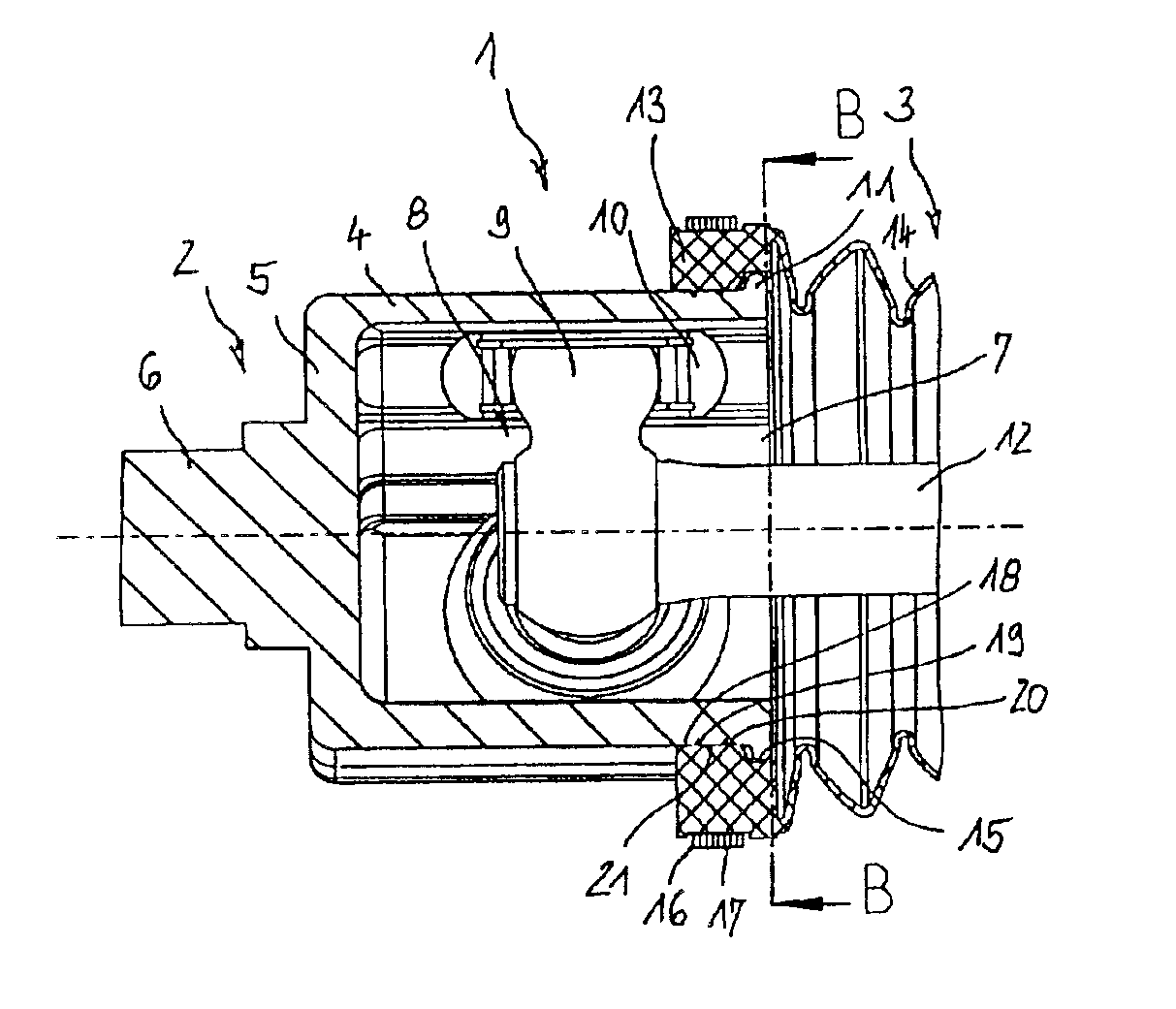
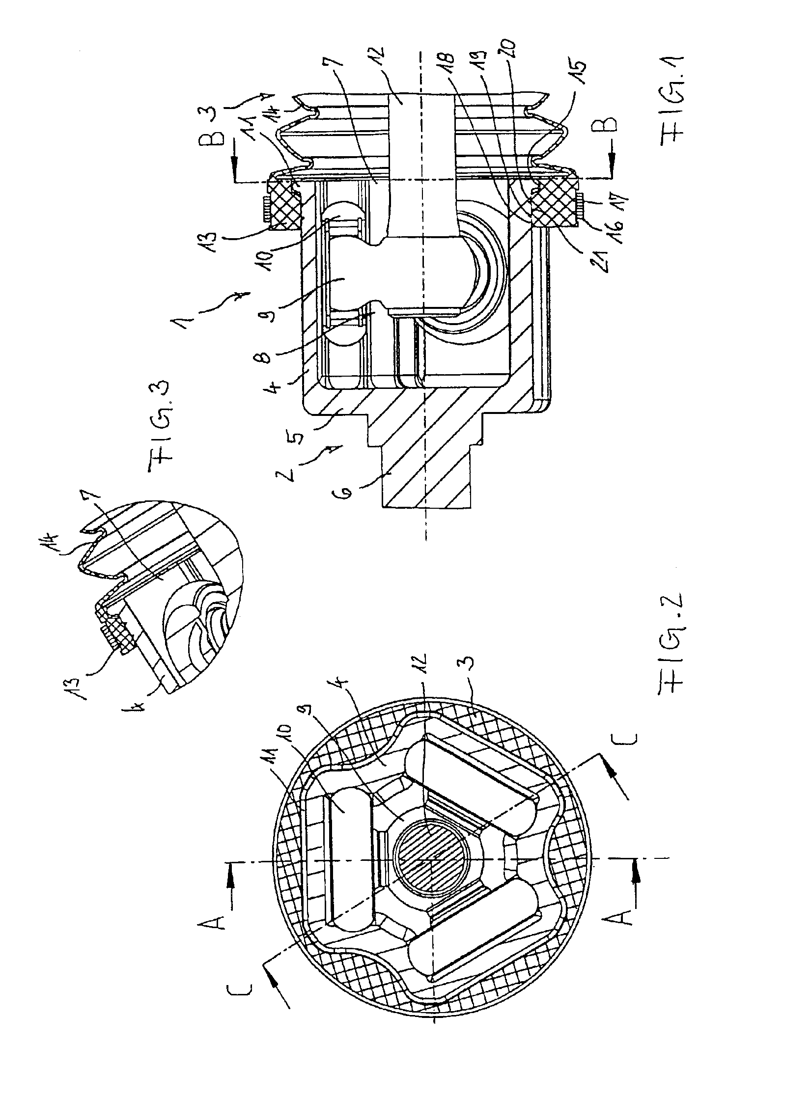
[0020]FIGS. 1 to 3 will be described jointly below. They show an inventive tripod joint assembly having a tripod joint 2 with a convoluted boot assembly 3. The tripod joint 2 comprises an outer joint part 4 which, in a cross-sectional view, has a clover-leaf-like outer and inner contour. At one end, the outer joint part 4 is closed by a base 5 to which there is attached a journal 6 for torque transmitting purposes. At the opposite axial end of the base 5 there is provided an aperture 7. In the region adjoining the aperture 7, the wall of the outer joint part 4 comprises a radially outwardly directed continuous bead 11 which can be produced during a process of forging or cold-forming the outer joint part 4. There is no need for the bead 11 to subsequently undergo chip-forming machining. The outer joint part 4 is engaged by an inner joint part 8 which comprises a tripod star 9 and roller assemblies 10. A shaft 12 is inserted into the tripod star 9 in a rotationally fast way. The assem...


PUM


Abstract

The invention relates to a tripod joint assembly, suited for the driveline of motor vehicles. It includes an outer joint part, rollers and an inner joint part which is connected to a shaft in a rotationally fast way, with an annular gap being formed between the shaft and the outer joint part, as well as a convoluted boot for sealing the annular gap. The outer joint part comprises a wall whose outer contour, in cross-section, deviates from the circular shape and which comprises a radially outwardly directed, circumferentially extending bead. The convoluted boot comprises an adapter ring and a convoluted portion connected to the adapter ring, with the adapter ring, on its radial inside, comprising an annular circumferential recess and, in its cross-section, being suitable for being fitted on to the outer joint part. When the adapter ring is fitted on to the outer joint part, the bead of the outer joint part engages the circumferential recess of the adapter ring in order to provide axial security.

Description

TECHNICAL FIELD[0001]The invention relates to a tripod joint assembly, particularly suited for the driveline of a motor vehicle. It comprises an outer joint part, rollers and a tripod star. The outer joint part, for torque transmitting purposes, is connectable to a shaft adjoining the outer joint part. The tripod joint assembly also comprises a convoluted boot for sealing the annular gap between the outer joint part and the shaft.BACKGROUND OF THE INVENTION[0002]From U.S. Pat. No. 4,927,678 there is known such a tripod joint assembly. On its radial outside, the outer joint part comprises a cylindrical annular seat and two annular beads extending in parallel thereto. The convoluted boot is designed to be rotationally symmetrical and, at the joint end, comprises a cylindrical collar as well as a convoluted portion adjoining same. When the convoluted boot is in a condition where it is slipped on to the outer joint part, the cylindrical collar of the convoluted boot is arranged on the n...

Claims


Application Information

Patent Timeline
Patent Type & Authority Patents(United States)
IPC IPC(8): F16D3/205F16D3/16F16D3/00F16D3/84F16J15/52F16J3/04
CPCF16D3/2055F16D3/845Y10T428/139Y10T428/19Y10S464/905
Inventor WETTE, JOACHIM
Owner GKN AUTOMOTIVE GMBH
Why Eureka
Try Eureka