Self-powered cordless mouse

a cordless mouse and self-powered technology, applied in the direction of instruments, electric digital data processing, cathode-ray tube indicators, etc., can solve the problems of limited mouse movement capabilities, cordless mouse suffers from its own disadvantage, etc., to achieve less prone to mechanical failure, extend the operating time, and be incorporated into the computer-pointing device inexpensively.

Inactive Publication Date: 2005-06-07
NACSON SABATINO
View PDF9 Cites 102 Cited by
  • Summary
  • Abstract
  • Description
  • Claims
  • Application Information

AI Technical Summary

Benefits of technology

[0021]The present invention provides advantages in that the computer-pointing device has an extended operating time as compared to prior art cordless mice due to the fact that movements of the computer-pointing device across a surface are converted to electrical power. This enables the computer-pointing device to be continually powered through motion of the computer-pointing device. The present invention also provides advantages in that since the power generating mechanism is of a simple design, it can to be incorporated into computer-pointing devices inexpensively and is less prone to mechanical failure than prior art self-powered cordless mice.

Problems solved by technology

Although this type of mouse is satisfactory for the most part, problems do exist.
Since the mouse is physically connected to the computer by the cord, the cord restricts the movement capabilities of the mouse.
However, the cordless mouse suffers from its own disadvantage.
Since the cordless mouse is not physically connected to the computer, the mouse is not able to draw power from the computer power supply.
Batteries of course require replacing when they run low and replacing batteries is inconvenient.
Also, batteries can drain at unexpected and inappropriate times creating user annoyance especially if the batteries drain while the user is in the middle of an important project.
Although this reference discloses a mouse including a mechanism to generate power, problems exist in that since the detection roller moves in two axial directions, the mouse is subject to mechanical failure.

Method used


Image

  • Self-powered cordless mouse
  • Self-powered cordless mouse
  • Self-powered cordless mouse

Examples


Embodiment Construction

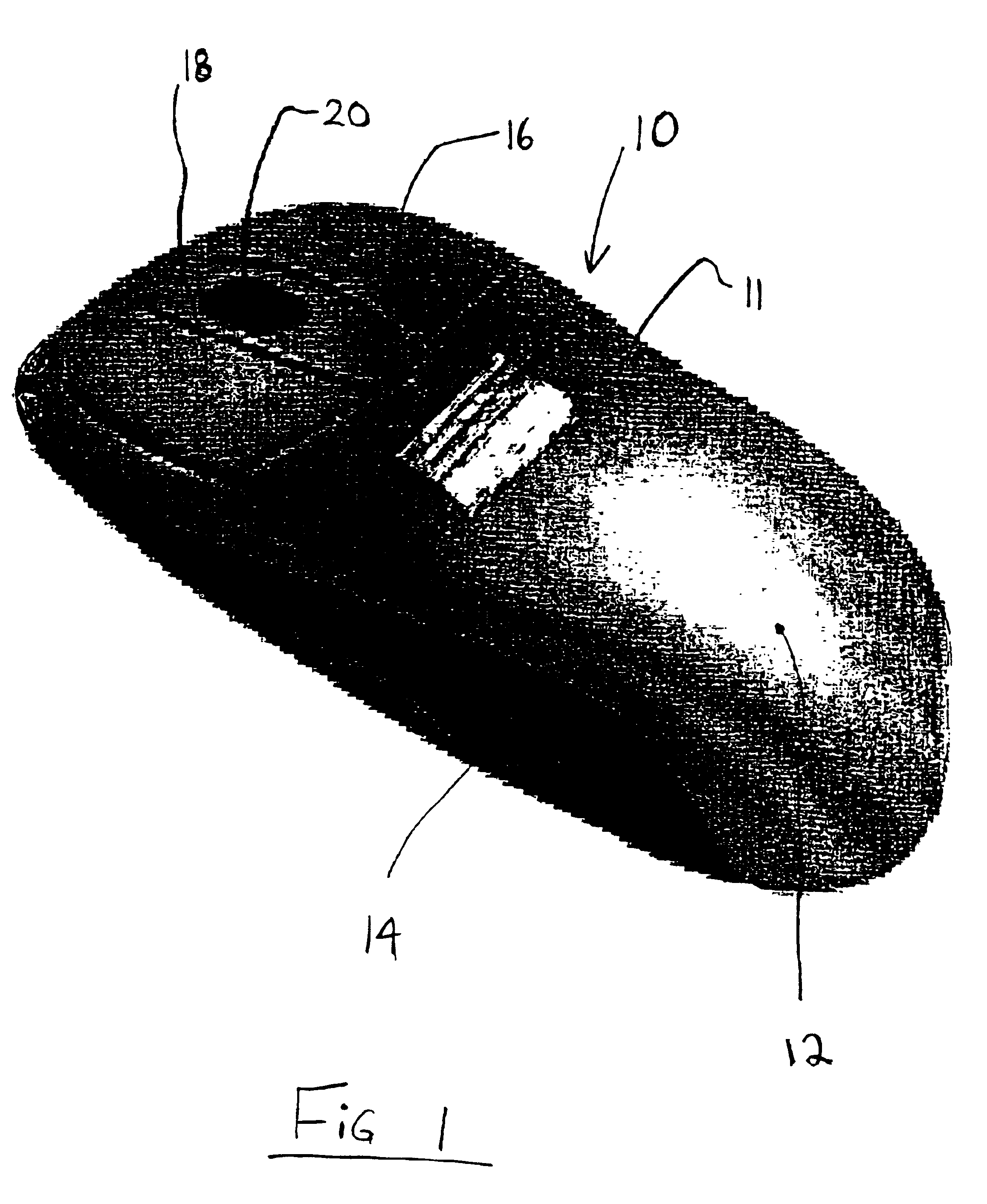
[0028]Turning now to FIG. 1, a computer-pointing device in the form of a cordless mouse is shown and is generally identified by reference numeral 10. The cordless mouse 10 includes a generally ovate housing 11 having a smooth, contoured upper surface 12 and a pair of side walls 14. Three buttons 16, 18 and 20 are provided on the upper surface 12 near its front end. The housing 11 is ergonomically shaped so that the hand of a user may fit comfortably around the mouse 10 with the tips of the user's fingers resting on the three buttons 16, 18 and 20. Although a three button mouse is shown, the mouse 10 may include any number of buttons.

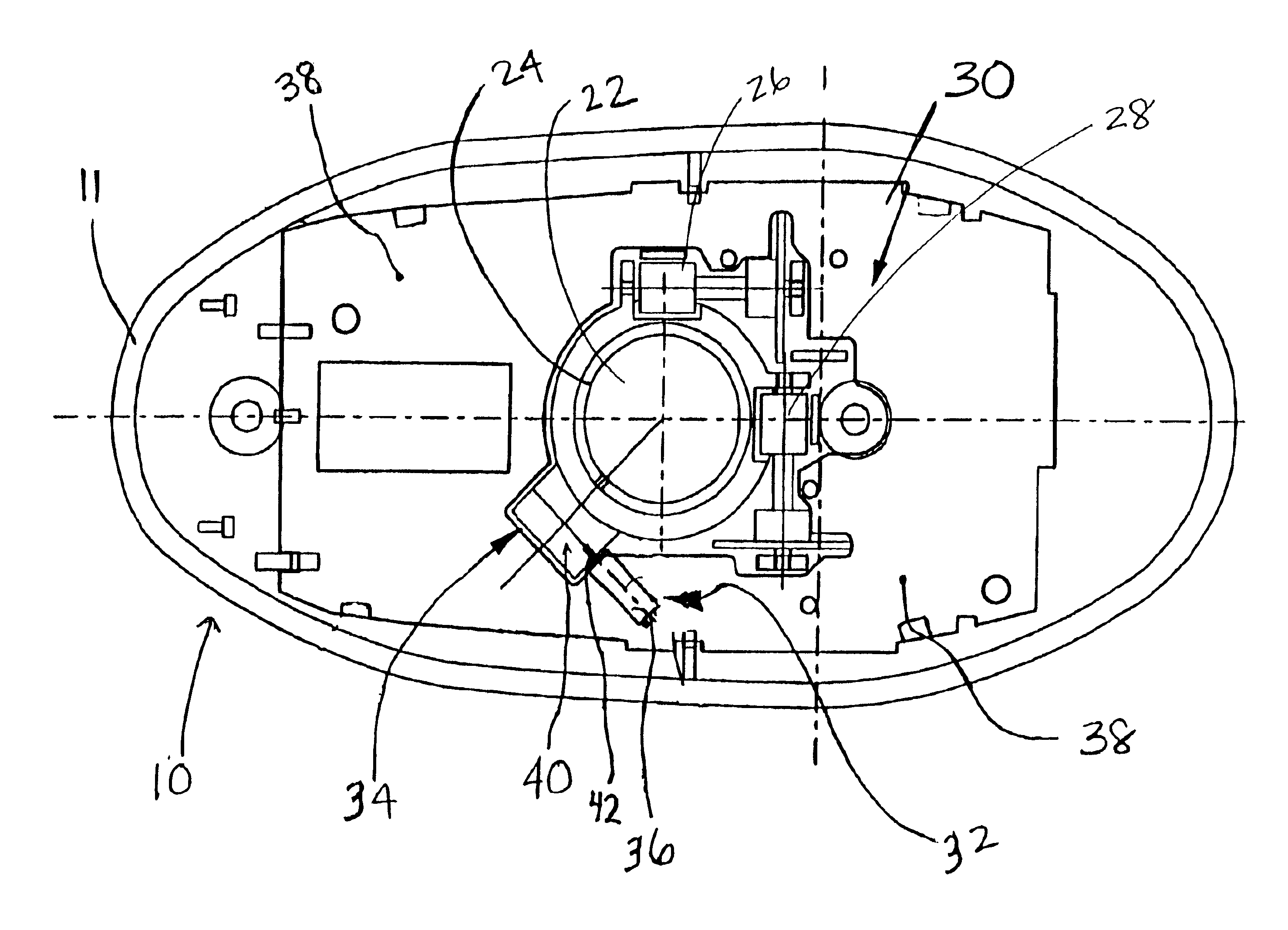
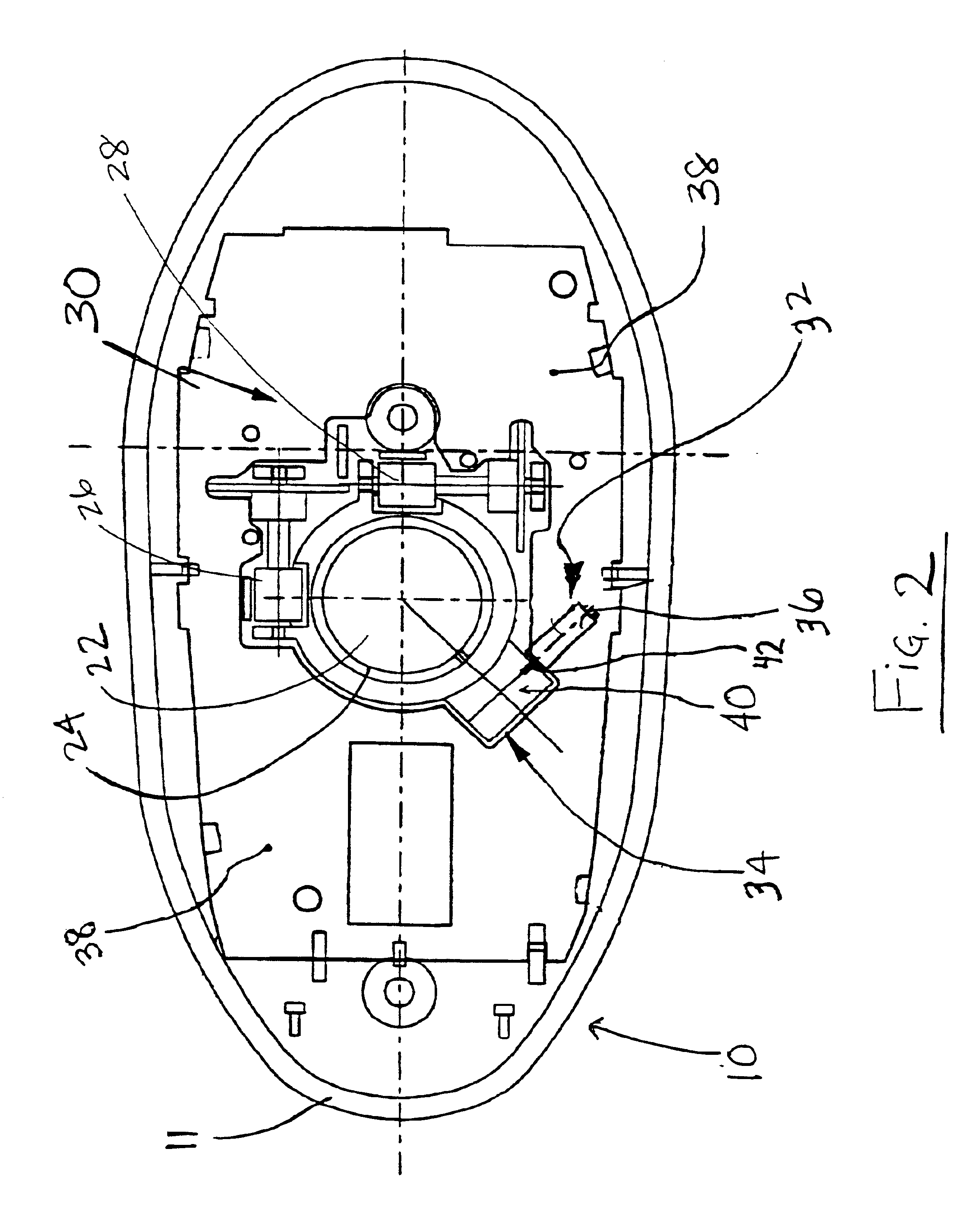
[0029]FIG. 2 shows the interior of the housing 11. As can be seen, a roller ball casing 24 is centrally disposed within the housing 11. The roller ball casing 24 accommodates a roller ball 22. Similar to a conventional mouse, a portion of the roller ball 22 is exposed through an opening in the base (not shown) of the housing 11 so that the roller ball 22...


PUM


Abstract

A self-powered computer-pointing device includes a housing and a roller ball accommodated within the housing. At least a portion of the roller ball is exposed through an opening in the housing to allow the roller ball to contact a surface on which the computer-pointing device rests. Movement of the computer-pointing device across the surface imparts rotation of the roller ball. A sensing mechanism senses movement of the roller ball and generates x-y movement signals corresponding to movement of the computer-pointing device across the surface. The sensing mechanism conveys the x-y movement signals to a host computer. A power generating mechanism is coupled to the roller ball and converts rotational movement of the roller ball into electrical energy that is used as power by the computer-pointing device.

Description

RELATED APPLICATIONS[0001]The present application is related to U.S. Provisional Patent Application Ser. No. 60 / 270,612 filed on Feb. 23, 2001 for an invention entitled “Self-Powered Cordless Mouse”.FIELD OF THE INVENTION[0002]The present invention relates in general to auxiliary input devices for computers and more specifically, to a self-powered computer-pointing device.BACKGROUND OF THE INVENTION[0003]Computer-pointing devices are often used in connection with computers to facilitate entry of user input and to enhance the functionality of the computers. One common type of computer-pointing device is the cord-based mouse. This type of mouse is connected to the computer by a cord and is moved over a pad to effect movement of the cursor displayed on the monitor of the computer. When the cursor is positioned at the desired location, actions can be invoked by clicking on one of the mouse buttons. Using the mouse in this manner allows a computer user to navigate through graphical user ...

Claims


Application Information

Patent Timeline
Patent Type & Authority Patents(United States)
IPC IPC(8): G06F3/033
CPCG06F3/03543
Inventor NACSON, SABATINO
Owner NACSON SABATINO
Why Eureka
Try Eureka