Energy storage device, method for manufacturing the same, and apparatus including the same

a technology of energy storage device and energy storage device, which is applied in the direction of cell components, final product manufacturing, sustainable manufacturing/processing, etc., can solve the problems of reducing the reliability of the energy storage device, difficult to apply the carbon nanotube electrode to the energy storage device having the above structure, and low electrical resistance of carbon nanotube electrodes, etc., to achieve the effect of improving long-term reliability, large current and large curren

Active Publication Date: 2010-07-15
PANASONIC INTELLECTUAL PROPERTY MANAGEMENT CO LTD
View PDF17 Cites 52 Cited by
  • Summary
  • Abstract
  • Description
  • Claims
  • Application Information

AI Technical Summary

Benefits of technology

[0026]By adopting the above-described configuration, the energy storage device of the present invention can prevent the reaction current from flowing by ionizing the catalyst metal or the substrate metal to cause the metal to flow out to the electrolytic solution.
[0027]With this, in the energy storage device including the carbon nanotube electrode, the reaction of flowing out the metal to the electrolytic solution can be prevented, so that long-term reliability can be improved. Further, since the reaction current decreases, the energy storage device can charge and discharge large current.
[0028]The energy storage device of the present invention can achieve the above effects. Therefore, conditions for mounting the energy storage device including the carbon nanotube electrode on a portable device including a wireless communication unit, an electronic device (such as an information processing terminal), a transporting device, and the like are satisfied. Especially, since the energy storage device of the present invention can discharge large current, it can improve the operating time of a portable device having wireless communication function, such as a mobile phone which instantaneously, significantly consumes energy and the operating time of an information processing terminal, such as a notebook computer. In addition, the energy storage device of the present invention can improve an accelerating performance of a transporting device, such as a hybrid car.

Problems solved by technology

In addition, since the carbon nanotube is connected to the current collector that is the substrate, the carbon nanotube electrode is very low in electrical resistance.
Then, a reaction current flows, and this decreases reliability of the energy storage device.
Therefore, it has been extremely difficult to apply the carbon nanotube electrode to the energy storage device having the above structure.

Method used


Image

  • Energy storage device, method for manufacturing the same, and apparatus including the same
  • Energy storage device, method for manufacturing the same, and apparatus including the same
  • Energy storage device, method for manufacturing the same, and apparatus including the same

Examples


example 1

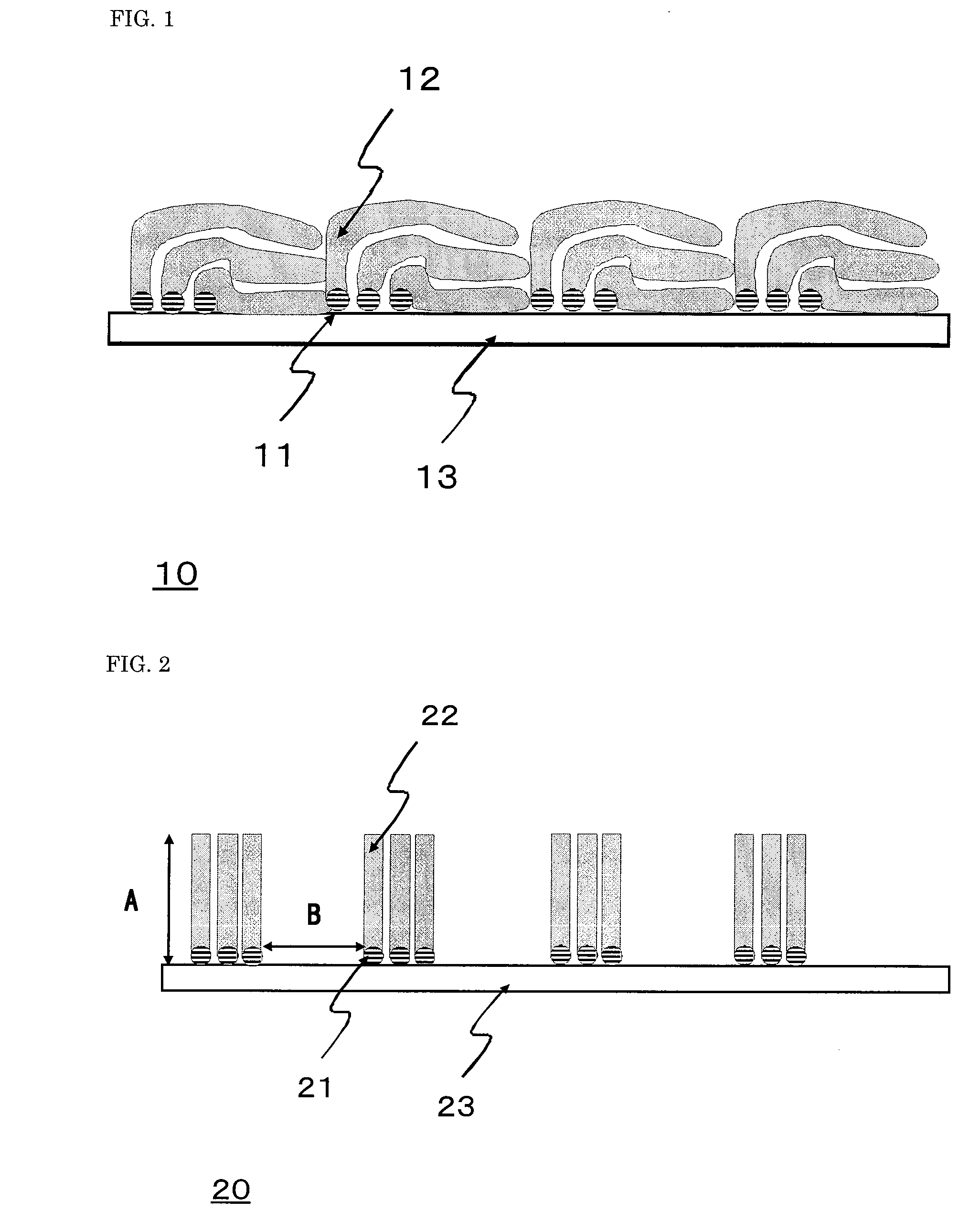
[0111]In a state where aluminum foil (15 μm in thickness) that was the electric conductor was covered with a striped patterning mask having a slit width of 400 μm and a slit-to-slit distance of 400 μm, Fe that was the catalyst metal used for the synthesis of the carbon nanotube was electron-beam-evaporated on the aluminum foil so as to have a thickness of 1 nm. Thus, a Fe film was formed on the surface of the electric conductor in a stripe pattern having the width of 400 μm and the distance of 400 μm.

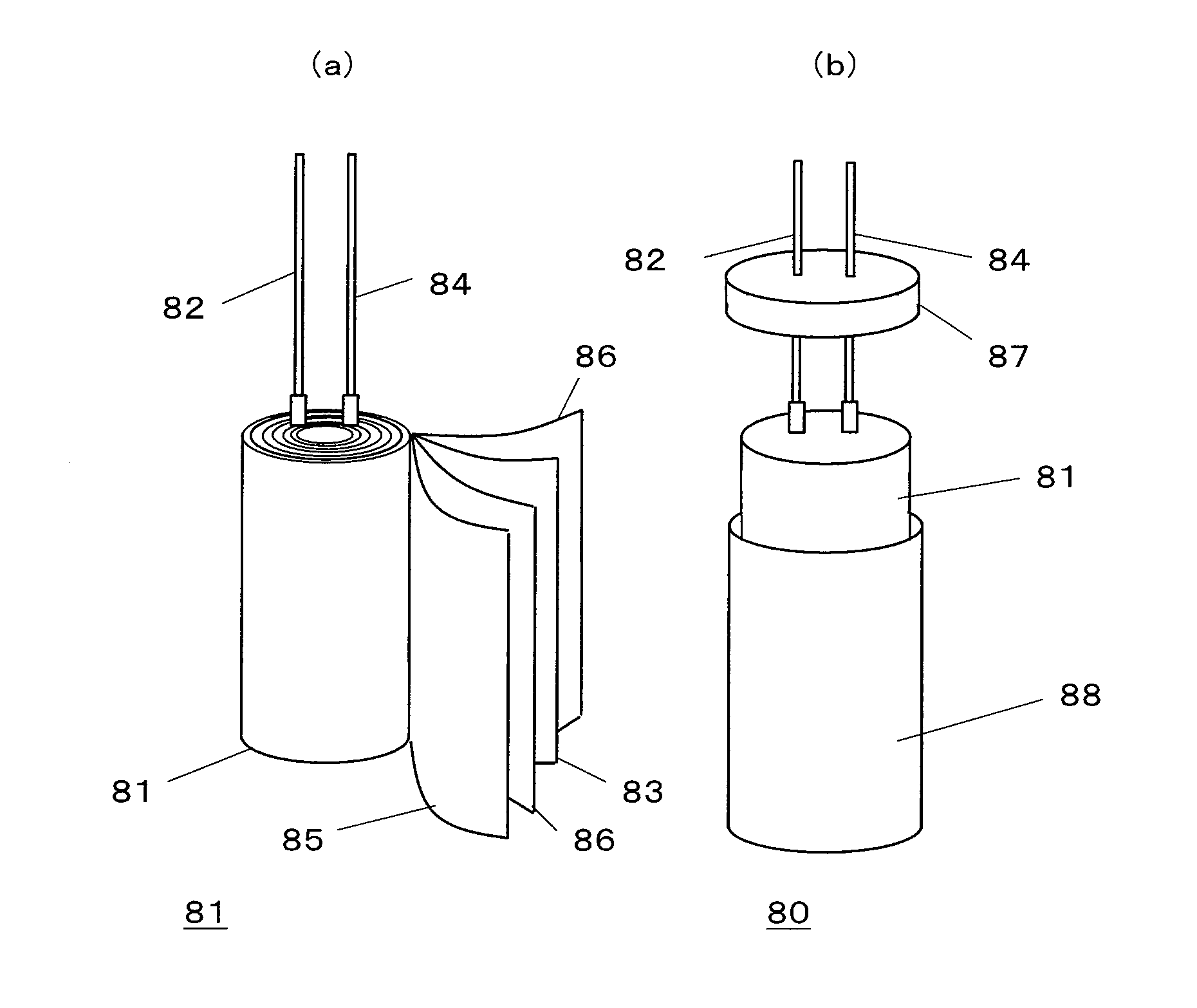
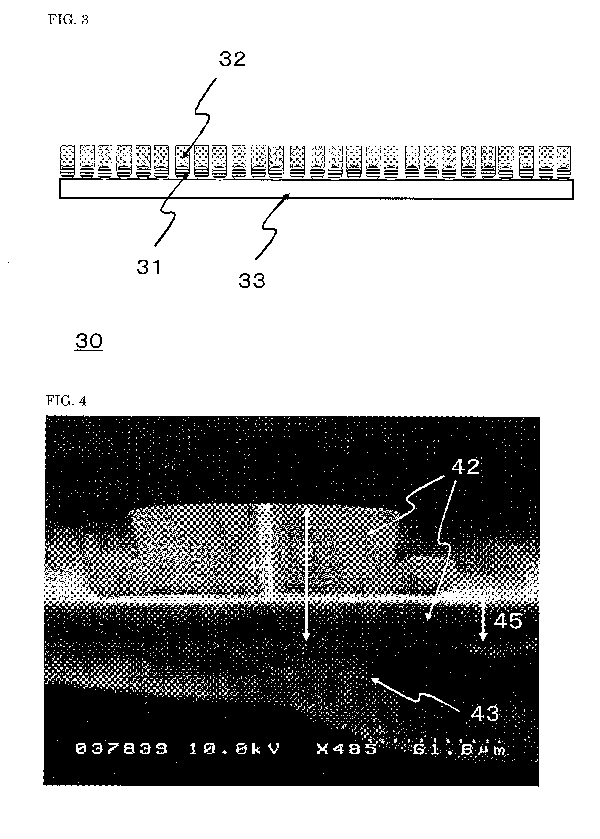
[0112]Plasma CVD was carried out with respect to the aluminum foil at 620° C. using ethylene as a carbon source. Thus, the layer of the carbon nanotubes was formed on the surface of the Fe film so as to have an average thickness of 403 μm. With this, bundles of the carbon nanotubes were vertically formed on the surface of the aluminum foil in a stripe pattern having the width of 400 μm and the distance of 400 μm. To be specific, one end of the bundle was connected to the aluminum foil.

[...

example 2

[0116]The rolled-structure energy storage device was manufactured in the same manner as in Example 1 except that the average thickness of the layer of the carbon nanotubes was changed to 522 μm. The reaction current was 11 μA when the applied voltage was +1.0V.

example 3

[0117]In a state where the aluminum foil (15 μm in thickness) that was the electric conductor was covered with a vertical-horizontal lattice patterning mask having 400-μm convex squares and a square-to-square distance of 400 μm, the water-repellent film was formed on the aluminum foil and dried. The water-repellent film was formed such that an operation of applying toluene diluted modified polypropylene (UNISTOLE R-200 produced by Mitsui Chemicals, Inc.) to the aluminum foil and carrying out heating for five minutes at 170° C. in an electric furnace was carried out twice.

[0118]Next, to form the film of Fe that was the catalyst metal used for the synthesis of the carbon nanotube by the dip coating, the aluminum foil was immersed in an iron acetate ethanol solution, pulled out from the solution at a rate of 4 cm / min, and dried at 400° C. for 30 minutes. Thus, the Fe film was formed on the surface of the electric conductor such that 400-μm squares were arranged at intervals of 400 μm.

[...


PUM

PropertyMeasurementUnit
volume densityaaaaaaaaaa
lengthaaaaaaaaaa
diameteraaaaaaaaaa

Abstract

The present invention provides a highly reliable energy storage device capable of preventing a reaction current from flowing in a carbon nanotube electrode by ionizing a catalyst metal or a substrate metal to cause the metal to flow out to an electrolytic solution. An energy storage device of the present invention includes: at least a pair of electrode bodies that are a cathode and an anode; and an electrolytic solution. At least one of the electrode bodies is configured such that a layer of carbon nanotubes is formed on an electric conductor. A coupling region where one ends of the carbon nanotubes are coupled to and electrically connected to the electric conductor and a non-coupling region where ends of the carbon nanotubes are not coupled to the electric conductor are formed on a surface of the electric conductor. The carbon nanotubes having one ends connected to the coupling region are toppled to cover a surface of the non-coupling region.

Description

TECHNICAL FIELD [0001]The present invention relates to an energy storage device, a method for manufacturing the energy storage device, and an apparatus including the energy storage device.BACKGROUND ART [0002]Two main types of an energy device are an energy storage device and an energy generating device. Typical examples of the energy storage device are an electrochemical capacitor and a battery, which have already been used in their appropriate markets. Examples of the electrochemical capacitor are: an electric double layer capacitor which uses an activated carbon as a polarizable electrode and utilizes only an electric double layer formed at an interface between a pore surface of the activated carbon and an electrolytic solution; and a redox capacitor which uses a transition metal oxide, such as ruthenium nitrate, whose valence continuously changes, and an electrically-conductive polymer which can be doped. Moreover, two main types of the battery are: a secondary battery which can...

Claims


Application Information

Patent Timeline
Patent Type & Authority Applications(United States)
IPC IPC(8): H01M4/583B05D5/12H01G9/155H01G9/00B82Y99/00H01G11/06H01G11/22H01G11/36H01G11/86H01M2/26H01M4/133H01M4/1393H01M4/58H01M4/587H01M4/66H01M10/0566H01M10/0585H01M10/0587H01M10/36
CPCH01G9/016H01G9/058H01G11/12H01G11/26H01G11/28H01G11/36Y02T10/7022H01M4/587H01M4/625H01M4/663H01M10/052Y02E60/13Y02T10/7011H01G11/86H01G11/22H01G11/74Y02E60/10Y02T10/70Y02P70/50
Inventor ASARI, TAKUMAKUMAGAI, HIRONORIHAYASHI, SHIGEOHASHIMOTO, YASUHIROKAWASHIMA, TAKAHIRO
Owner PANASONIC INTELLECTUAL PROPERTY MANAGEMENT CO LTD
Why Eureka
Try Eureka