Method of Detecting Electrons, an Electron-Detector and an Inspection System

a technology of electron detector and inspection system, applied in the direction of instruments, electrical equipment, radiation measurement, etc., can solve the problems of scintillator plate quality loss, incident electron conversion into light beams at a lower efficiency, and loss of quality of scintillator pla

Active Publication Date: 2015-03-26
CARL ZEISS MICROSCOPY GMBH
View PDF2 Cites 43 Cited by
  • Summary
  • Abstract
  • Description
  • Claims
  • Application Information

AI Technical Summary

Benefits of technology

[0026]The images of the locations of incidence of the electron beams are perceptible on the image detected by the light-optical camera. By analyzing the imag

Problems solved by technology

The inventors found out that this scintillator plate suffers a loss of quality due to the incident electron beams at increasing time of operation and, then, the incident electrons are converted into light beams at a lower efficiency.
This loss of quality of the scintillator plate may, for example, be caused by a loss of quality of the

Method used


Image

  • Method of Detecting Electrons, an Electron-Detector and an Inspection System
  • Method of Detecting Electrons, an Electron-Detector and an Inspection System
  • Method of Detecting Electrons, an Electron-Detector and an Inspection System

Examples


Embodiment Construction

[0034]In the exemplary embodiments described below, components that are alike in function and structure are designated as far as possible by alike reference numerals. Therefore, to understand the features of the individual components of a specific embodiment, the descriptions of other embodiments and of the summary of the disclosure should be referred to.

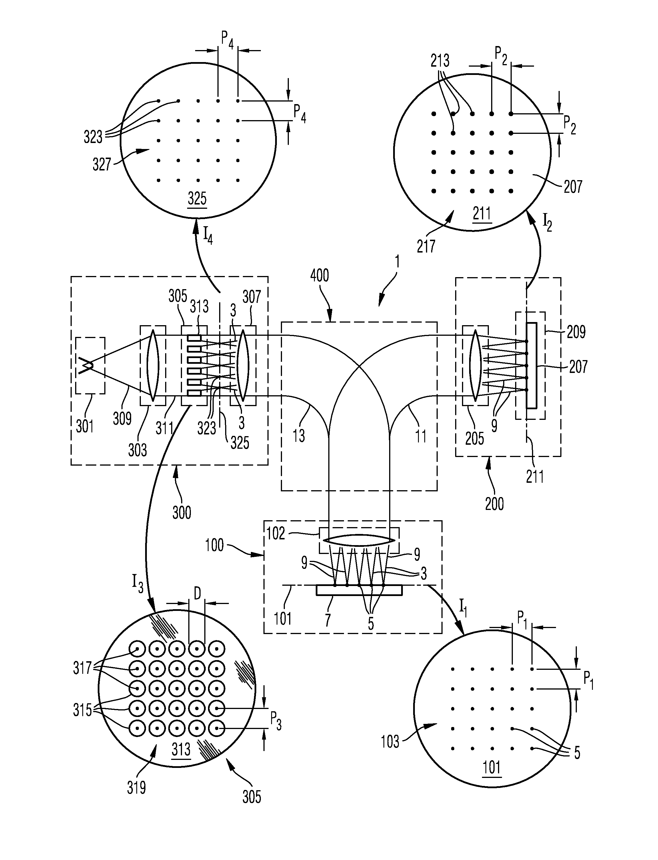
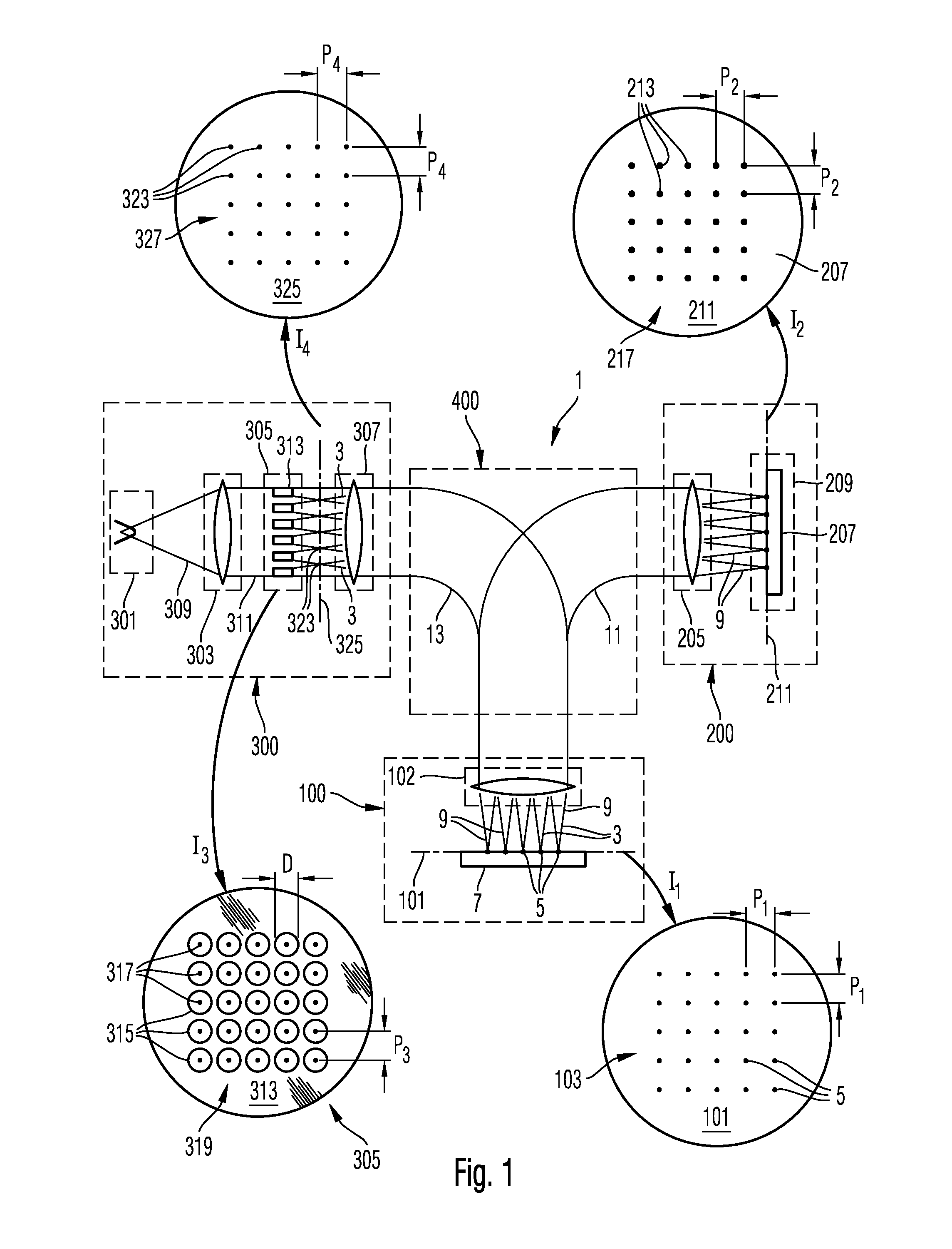
[0035]FIG. 1 is a schematic illustration of a multi-beam inspection system using a plurality of beams of charged particles. The inspection system generates a plurality of beams of charged particles incident onto an object to be analyzed in order to there generate electrons emitted from the object and subsequently being detected. The inspection system 1 is a type of scanning electron microscope (SEM) using a plurality of primary electron beams 3 in order to generate a plurality of electron beam spots 5 on a surface of the object 7. The object to be analyzed 7 may be of any kind and comprise, for example, a semiconductor wafer, a biol...


PUM


Abstract

An electron-detector comprises a scintillator plate 207, electron optics 204 for directing a plurality of electron beams 9 onto the scintillator plate so that the electron beams are incident onto the scintillator plate at locations of incidence disposed at a distance from each other, a light detector 237 comprising a plurality of light receiving areas 235 disposed at a distance from each other, and light optics for generating a first light-optical image of at least a portion of the scintillator plate at a region 243 where the light receiving areas of the light detector are disposed so that, by the imaging, each of the locations of incidence is associated with a light receiving area; and wherein the electron optics comprise an electron beam deflector 255 for displacing the locations of incidence of the electron beams on the scintillator plate in a direction orthogonal to a normal 249 of a surface 208 of the scintillator plate.

Description

CROSS-REFERENCES TO RELATED APPLICATIONS[0001]The present application claims priority of Patent Application No. 10 2013 016 113.4, filed Sep. 26, 2013 in Germany, the entire contents of which are incorporated by reference herein.FIELD[0002]The invention relates to a method of detecting electrons, an electron detector and an inspection system. In particular, the invention relates to a method of detecting a plurality of electron beams, an electron-detector and a multi-beam inspection system detecting intensities of a plurality of electron beams.[0003]From WO 2005 / 024881, an inspection system is known in which a plurality of beams of charged particles are directed onto an object. The system is an electron microscope in which a plurality of primary electron beams are focused parallel to each other in order to form an array of foci on the object. Electrons emerging from the object due to the charged particles incident onto the foci are formed by electron optics to a respective array of e...

Claims


Application Information

Patent Timeline
IPC IPC(8): H01J37/244H01J37/22H01J37/28
CPCH01J37/244H01J37/28H01J2237/15H01J2237/2443H01J2237/24507H01J37/226H01J37/285H01J2237/2857
Inventor ZEIDLER, DIRKJACOBI, JORG
Owner CARL ZEISS MICROSCOPY GMBH
Why Eureka
Try Eureka