Method for producing an eyelet

a technology of eyelets and eyelets, applied in metal-working equipment, metal-working equipment, manufacturing tools, etc., can solve the problems of cumbersome and prone to errors, complicated and cumbersome connection of machined parts or plates, and the need for expensive machinery and trained personnel, so as to simplify the various work steps and make the method more profitable.

Inactive Publication Date: 2005-06-14
WELSER PROFILE AG
View PDF13 Cites 6 Cited by
  • Summary
  • Abstract
  • Description
  • Claims
  • Application Information

AI Technical Summary

Benefits of technology

[0009]It is thus the object of the present invention to simplify the various work steps and thus to make the method more profitable.

Problems solved by technology

A disadvantage with known methods is that the machined parts or plates to be connected must be predrilled individually in a separate work step.
Methods of this kind are unprofitable due to the extra work steps and due to the different drill holes of the machined parts or plates, depending on intended usage, it is cumbersome and prone to error.
For this, however, expensive machinery and trained personnel are required.

Method used


Image

  • Method for producing an eyelet
  • Method for producing an eyelet
  • Method for producing an eyelet

Examples


first embodiment

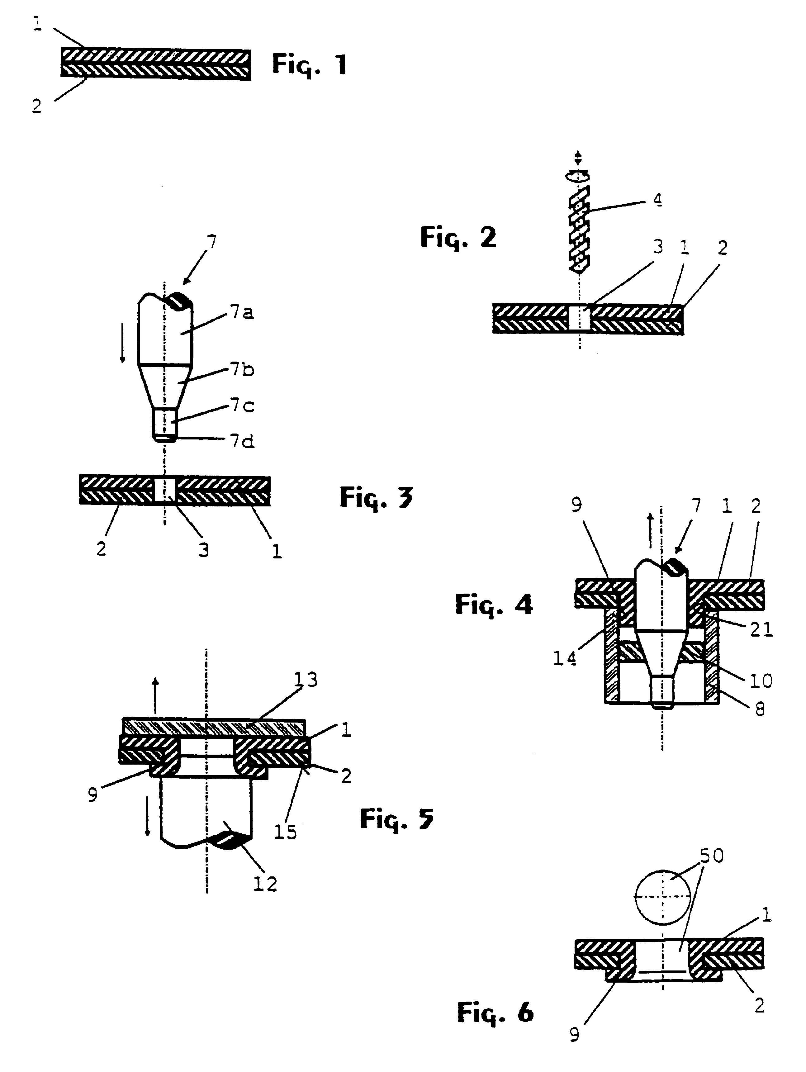
[0032]Here below, the first embodiment will be explained on the basis of the schematic FIGS. 1 through 6 showing in each case the workpieces and tools in cross-section.

[0033]FIG. 1 shows plate-shaped workpieces 1 and 2, of different thickness, piled on top of each other and which are to be joined.

[0034]FIG. 2 shows how a penetration drilling 3 through workpieces 1, 2 is accomplished by means of a drill 4 through vertical feed through the pile composed of workpieces 1 and 2. The diameter of the penetration drilling 3 in this embodiment example is constant throughout. Workpieces 1 and 2 are made of steel but can consist, independently from each other, of different metal materials.

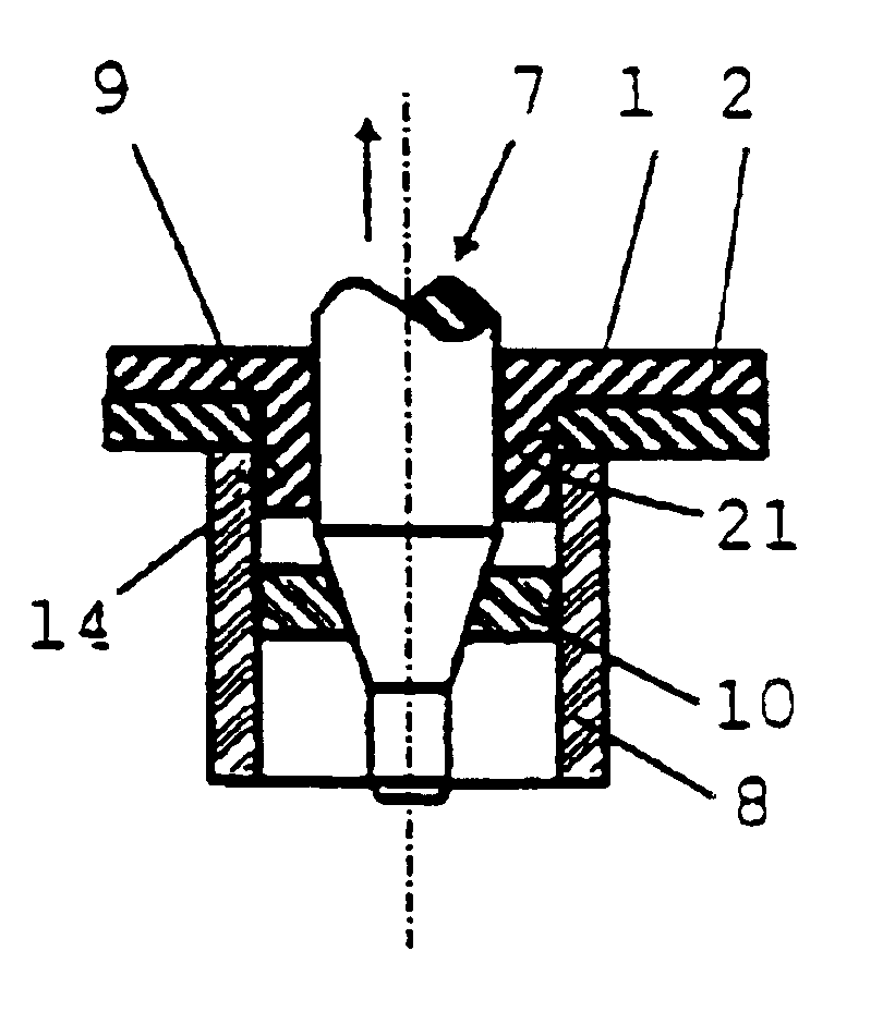
[0035]In FIG. 3, the dynamically balanced rim hole punch 7 is shown consisting of several sections 7a, 7b, 7c and 7d and fed through penetration drilling 3. The phase 7d at the front end of the rim hole punch 7 serves for more easily driving the rim hole punch 7 into the penetration drilling 3. The connecting...

second embodiment

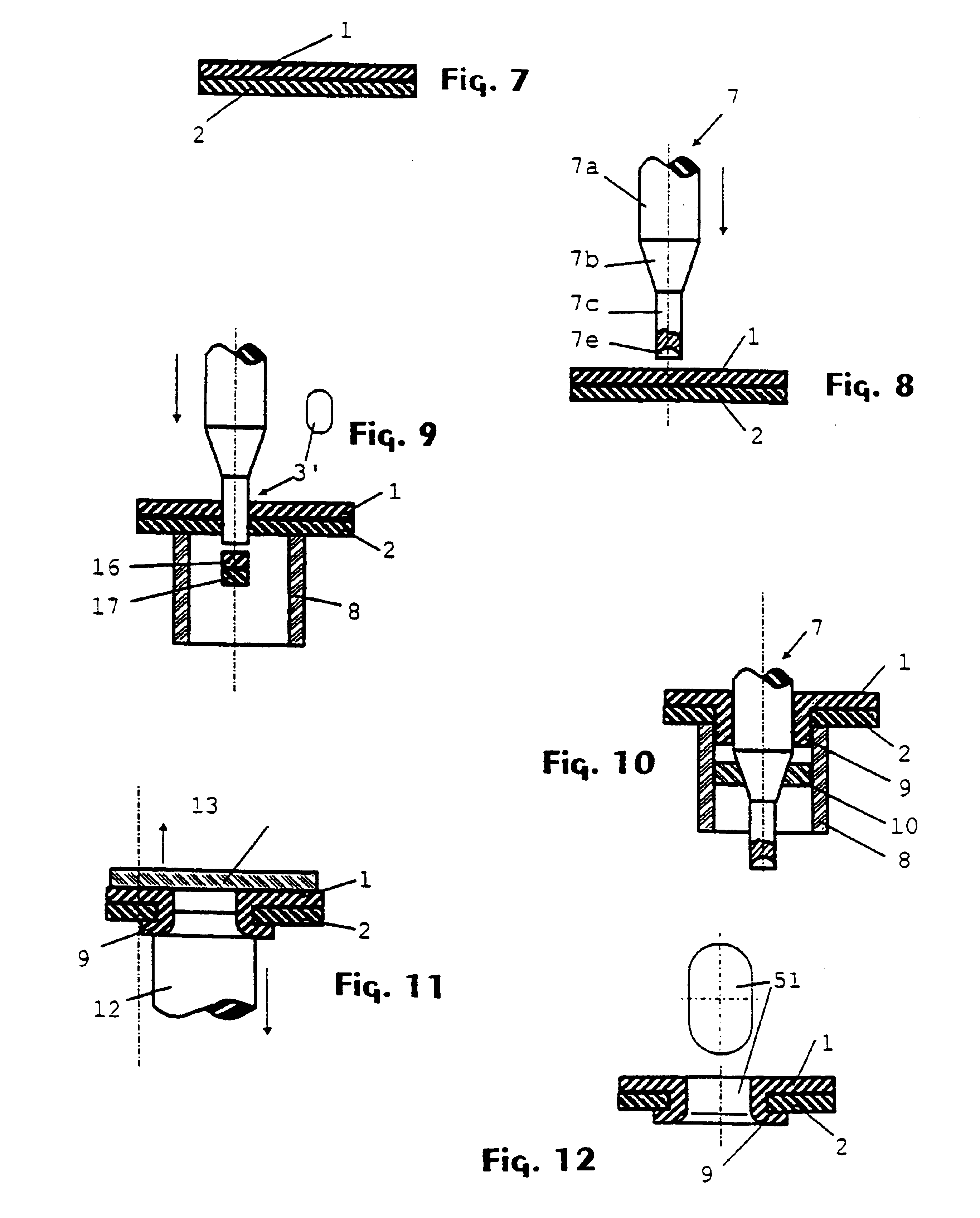
[0042]FIG. 7 corresponds to FIG. 1, workpieces 1 and 2 are, nonetheless, made of aluminium in the

[0043]In FIG. 8, a rim hole punch 7 is shown that has been modified contrary to the first embodiment and that is led through workpieces not drilled in this embodiment. Instead of phase 7d, the rim hole punch has a punched section 7e. The punched section 7e produces, during the rim hole punch's (7) feed movement, the penetration opening 3′ in an oblong hole shape. The penetration opening 3′ serves to prevent the accumulation of too much material in the rim hole 9. If too much material is actually in rim hole 9, then the material must flow particularly strongly. This generally results in a breakthrough of the rim hole and in riveted joints with reduced resistance to strains. During feed with rim hole punch 7, workpiece 2 is supported by matrix 8. However, it is also feasible that during production of penetration opening 3′, workpiece 2 is supported by a smaller matrix located inside matrix...


PUM

PropertyMeasurementUnit
tensile stressesaaaaaaaaaa
areaaaaaaaaaaa
timeaaaaaaaaaa

Abstract

Method for production of an eyelet, during connection of workpieces where material of an outermost workpiece is pulled through openings in the other workpieces, using a single feed movement of rim hole or eyelet punch to both shape the eyelet from the one workpiece and generate the openings, in the other workpieces by breaking out one or more pieces of materials, providing a reduction in the number of operating steps and simplifying such steps.

Description

REFERENCE TO RELATED APPLICATIONS[0001]This disclosure claims the benefit of the filing date of International Application No. PCT / EP99 / 00217, having an international filing date of Jan. 15, 1999, which designated the United States of America, and this disclosure is the United States national stage of that international application. This disclosure further claims priority to German patent application No. 198 10 367.0, filed Mar. 10, 1998.FIELD OF THE INVENTION[0002]The invention refers to a method for producing a rim hole or eyelet through a pile of at least two plate-shaped work pieces and in which, by means of a rim hole punch basically driven through the pile vertically, material of one plate-shaped work piece facing the rim hole punch is pulled through an opening of the other plate-shaped work piece, whereby the inner contours of the opening basically correspond to the outer contours of the rim hole and is formed in one single feed motion of the rim hole punch, the rim hole as we...

Claims


Application Information

Patent Timeline
Patent Type & Authority Patents(United States)
IPC IPC(8): B21C37/29B21C37/15B21D39/03B21J15/00B21J15/04B21J15/02
CPCB21C37/292B21D39/034B21J15/02B21J15/046Y10T29/49915Y10T29/49908Y10T29/49835Y10T29/49936
Inventor PLANK, OTTO
Owner WELSER PROFILE AG
Why Eureka
Try Eureka