
Multiturn pulley liquid level sensor device

a liquid level sensor and pulley technology, applied in the direction of level indicators by floats, etc., can solve the problems of prone to failure of optical encoders, and inability to carry out visual inspection, so as to reduce the volume, improve performance, and reduce the cost

Active Publication Date: 2018-04-24
MULTIDIMENSION TECH CO LTD
View PDF17 Cites 0 Cited by
  • Summary
  • Abstract
  • Description
  • Claims
  • Application Information

AI Technical Summary

Benefits of technology

[0007]An objective of the present invention is to provide a liquid level sensor device with a small volume, a low cost, high performance and high measurement precision, so as to overcome the above problems existing in the prior art.
[0031]Preferably, the gear speed-increasing or speed-reducing device is a friction wheel coupling that can reduce friction, wherein the friction wheel coupling includes a hub and a wheel shaft, and a rotating shaft thereof is different from the rotating shafts of the top pulley and the rotating wheels.
[0035]Compared with the prior art, the present invention has the following beneficial effects:
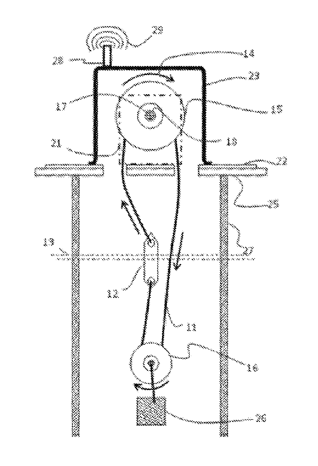
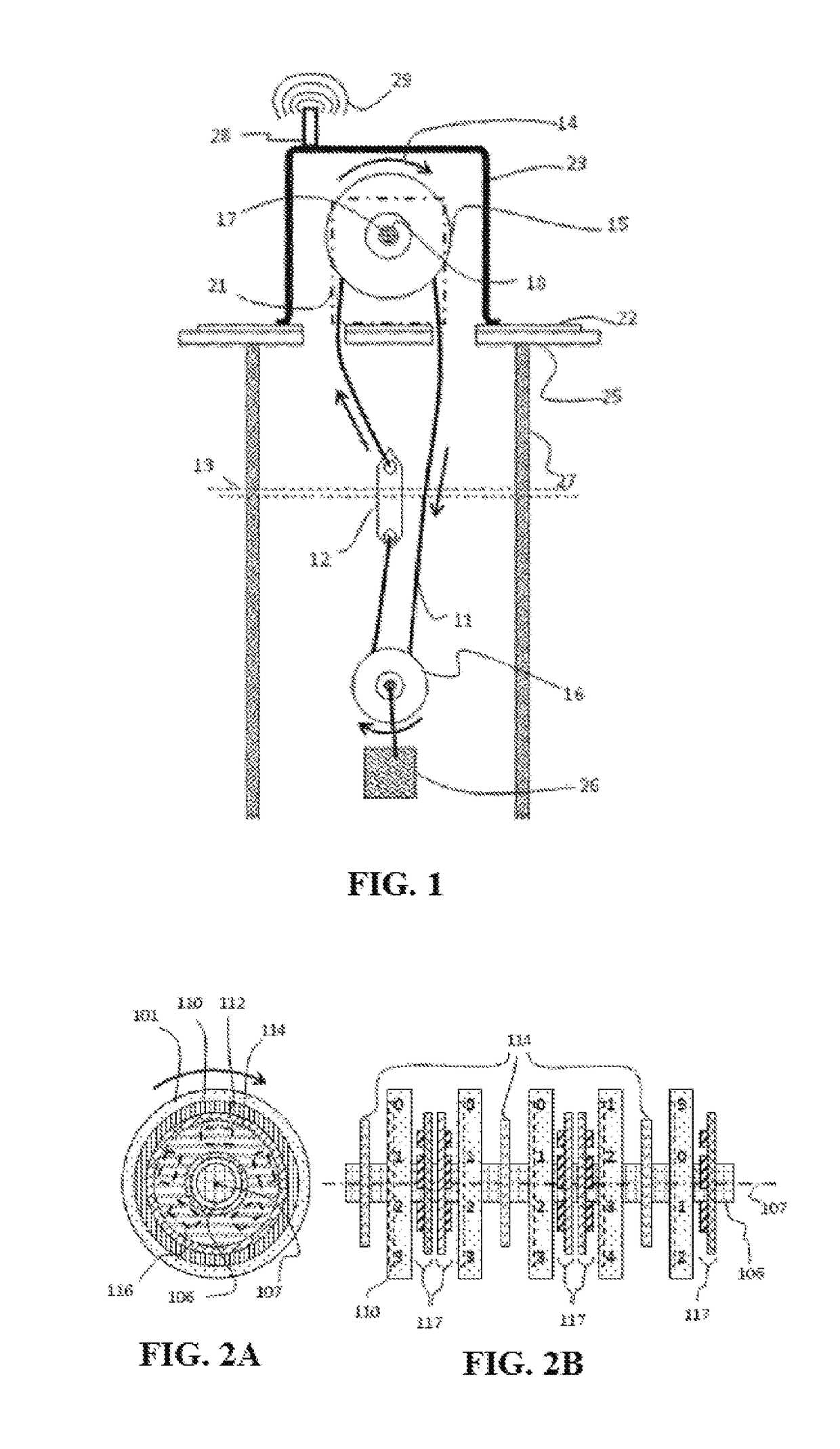
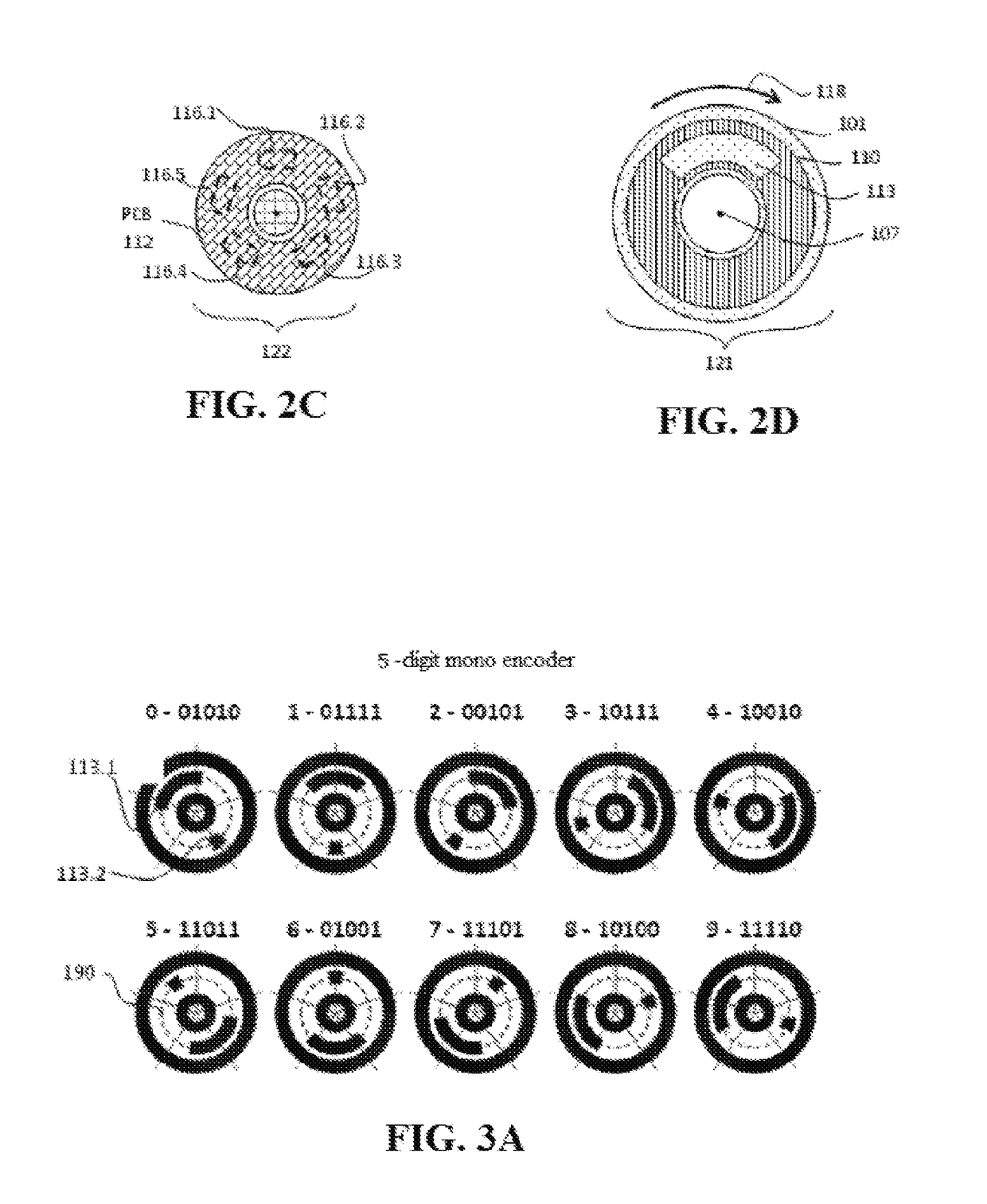
[0036]The present invention not only can reduce the volume and decrease the cost, but also can improve performance. In addition to electronic output, visual output is also provided, and the visual output is embodied in the form of numbered rotating wheels and LED display. Output precision is increased by one order of magnitude for each additional encoded rotating wheel, and in principle, there is no limitation to the number of useable encoded rotating wheels. A set of step-up or step-down gears are provided to calibrate actual depths that have been possibly measured, and such an absolute magnetic rotation encoding technology can avoid errors resulting from harsh environments.
[0037]The present invention uses less physical space, has a simpler control circuit, and provides users with more methods to obtain information related to the liquid level. The sensor is more reliable, the liquid level measurement precision is higher, the requirement for the power supply is lower, and a battery smaller than 5 V can be used to supply power.

Problems solved by technology

The liquid level sensing systems in the prior art have some defects.
They provide electronic output signals, but visual inspection cannot be carried out.
The encoders are based on optics, and the optical encoders are prone to failure as a result of getting dirty.
At present, there is no method that can be applied to make these devices widely applicable to measuring liquid levels in a well, and there is no method for improving the precision of this type of liquid level measurement.

Method used


Image

  • Multiturn pulley liquid level sensor device
  • Multiturn pulley liquid level sensor device
  • Multiturn pulley liquid level sensor device

Examples


embodiment 1

[0068]an encoder has 5 rotating wheels, each rotating wheel has 5 sensors, a pulley is provided on the top, within a sealed housing, sealed electricity is fed through to an external electronic communication unit, and a weight is provided on a bottom pulley.

[0069]The first embodiment of the present application is as shown in FIGS. 5, 6 and 7. FIG. 5 is a front sectional view. A coupler 30 provides a mechanical connection between a pulley shaft 18 and an encoder rotation shaft 106. A bracket 21 supports the weight of the pulley shaft 18 and the encoder rotation shaft 106 and an additional acting force, and the bracket 21 is installed to the top of a housing bottom plate 22. 5 sets of rotating wheel PCBs 112 are installed onto a system PCB 31, the rotating wheel PCBs 112 provide electrical connections between the sensor 116 and the system PCB 31, and they can also provide some mechanical supports for other parts of the encoder device, for example, the permanent magnet 114.

[0070]The hou...

embodiment 2

[0076]other contents are the same as those in Embodiment 1 except that a protective tube is added.

[0077]Although not shown in FIG. 5, FIG. 6 and FIG. 7, a structure may be added nearby a fastening rope device below the container wall 25, for example, the protective tube 27 shown in FIG. 1. The purpose of adding such a structure is to maintain the float and other device components in proper positions of the well or the container and, at the same time, far away from any object that damages movement.

embodiment 3

[0078]other contents are the same as those in Embodiment 1 except that the sealed housing has a transparent cover from which the digits on the rotating wheels can be read directly.

[0079]The housing top cap 23 can be made of such a transparent material as plastic, and values on the encoder rotating wheels 101-105 can be read directly without removal of the top cap. In addition, if the housing top cap 23 is not transparent, it is also feasible to dispose a small transparent window thereon.


PUM


Abstract

A multiturn pulley liquid level sensor device for measuring a liquid level in a well and in a container, comprising a mechanical float which is fastened to a fastening rope and which can slide up and down. The fastening rope is installed on one or more pulleys, and as the float moves up and down, the pulley rotates back and forth. One pulley is mechanically coupled to one digital absolute magnetic rotation encoder device, and the encoder device is used for monitoring the total rotation angle of the pulley in real time. By way of using an algorithm, the total rotation angle of the pulley is converted into a distance from the bottom to calculate the height of a liquid level. A multiwheel encoder has two reading types, i.e., one is an electrical signal reading type, and the other is an optical signal reading type. The electronic output of said encoder may be used as input to an industrial control system, or be sent via communications link to a remote or the internet. The precision of the level measurement is determined by the number of encoder wheels. A mechanical gear or belt can adjust the total number of pulley turns corresponding to the full range of liquid level measurement.

Description

PRIORITY CLAIM TO RELATED APPLICATIONS[0001]This application is a U.S. national stage application filed under 35 U.S.C. § 371 from International Application Serial No. PCT / CN2014 / 087545, which was filed 26 Sep. 2014, and published as WO2015 / 043506 on 2 Apr. 2015, and which claims priority to China Application No. 201310369292.1, filed 26 Sep. 2013, which applications and publication are incorporated by reference as if reproduced herein and made a part hereof in their entirety, and the benefit of priority of each of which is claimed herein.TECHNICAL FIELD[0002]The present invention relates to a sensor device that can measure a liquid level in a container or a well, and in particular, to a liquid level sensor that measures a liquid level by using a combination of a pulley, a fastening rope, an absolute magnetic rotation encoder and other devices.BACKGROUND ART[0003]In the technical field of liquid level sensors, two patent documents relevant to the present application which describe t...

Claims


Application Information

Patent Timeline
Patent Type & Authority Patents(United States)
IPC IPC(8): G01F23/46G01F23/40
CPCG01F23/40G01F23/46
Inventor DEAK, JAMES GEZATONDRA, MARK C.
Owner MULTIDIMENSION TECH CO LTD
Learn More