
Battery state estimation using electrode transient model

a transient model and battery technology, applied in the field of electric systems, can solve the problems of complex determination of the above-mentioned ocv curve and real-time state estimation problem, and the concentration of each species is not necessarily uniform through a given electrode, and achieves the effect of minimal over-current computational burden associated with the present method

Active Publication Date: 2021-03-16
GM GLOBAL TECH OPERATIONS LLC
View PDF7 Cites 0 Cited by
  • Summary
  • Abstract
  • Description
  • Claims
  • Application Information

AI Technical Summary

Benefits of technology

[0001]The present disclosure relates to electrical systems employing rechargeable battery packs. Aspects of the disclosure pertain to the real-time estimation of the battery pack's equilibrium cell voltage, and the use of the same to estimate the pack's state of charge (SOC) or state of power (SOP). As commonly used in the art, the term “state of charge” is the battery energy, usually expressed as a percentage, that remains available for use in the battery's various cells relative to a respective SOC of a fully-charged battery pack. “State of power” describes the remaining power capability of the battery pack after a predefined duration of maximum use, e.g., 2 s or 10 s. Monitoring of the battery state enables optimal control and power flow decision making to occur during charging or discharging operations. Thus, electrified vehicles, powerplants, and other electrified systems benefit from use of a battery management system that is better able to track the evolving internal state or states of the battery pack between actual state measurements. The present disclosure lends itself to supporting such applications.
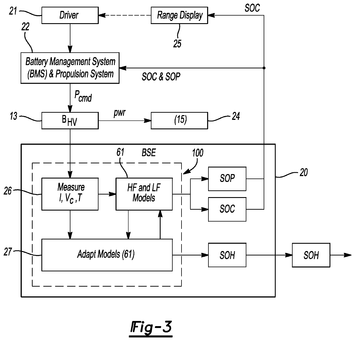
[0011]In particular, the controller used in the present strategy addresses the potential problem of such transient effects using a porous electrode transient (PET) model as part of a collective model set. The PET model is configured to model low-frequency transient voltage effects occurring in the battery cells during charging or discharging. The PET model considers charge distribution at a multitude of discretized “layers” of a given electrode, e.g., the negative electrode. As few as three such discretized layers may be used in some embodiments, with up to seven to ten such layers being sufficient in other embodiments, and thus the excess computational burden associated with the present method is minimal. More or fewer discretized layers may be modeled as needed via the PET model to provide a desired computational load-performance tradeoff.

Problems solved by technology

The nature of the physicochemical processes governing the flow of chemical species is such that the concentration of each species is not necessarily uniform through a given electrode.
Such non-uniformity results in differences in the local SOC at various points in the electrode material.
Accuracy of determination of the above-noted OCV curve and real-time state estimation problem are complicated by the presence of circuit resistance and voltage transients, as well as charge transfer physics occurring within the battery cell itself, all of which may combine to render existing SOC / SOP estimation techniques less than optimal under certain conditions.
If the transient voltage effect is not properly taken into account, an inaccurate real-time battery state estimation may result.
Thus, discrete / single-layer bulk estimations of the battery cell's SOC may result in less than optimally accurate real-time battery state estimations.
This results in transients in the voltage measured at the terminals.

Method used


Image

  • Battery state estimation using electrode transient model
  • Battery state estimation using electrode transient model
  • Battery state estimation using electrode transient model

Examples


Embodiment Construction

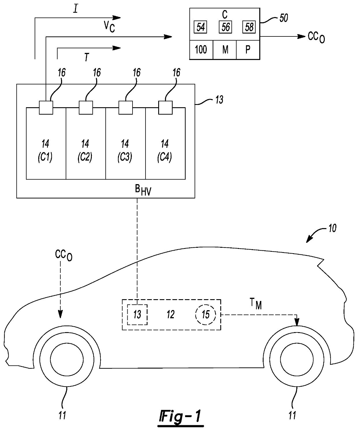
[0029]Referring to the drawings, wherein like reference numbers refer to like components, FIG. 1 depicts an example vehicle 10 having a set of drive wheels 11 powered via an electrical system 12. Power flow to or from the electrical system 12 is managed by a controller (C) 50, e.g., a battery system manager or other control device(s), with the controller 50 regulating operation of the electrical system 12 via a set of output signals (arrow CCO). The vehicle 10 may be optionally embodied as a hybrid electric vehicle or a battery electric vehicle in which the electrical system 12 ultimately generates and delivers propulsion torque to the drive wheels 11. While the vehicle 10 is described hereinafter as one example type of high-energy system that may benefit from the present teachings, vehicles may be envisioned other than the illustrated motor vehicle 10, e.g., aircraft, marine vessels, or rail vehicles, as well as stationary or mobile powerplants, platforms, robots, etc., without lim...


PUM

PropertyMeasurementUnit
thicknessaaaaaaaaaa
porosityaaaaaaaaaa
electricalaaaaaaaaaa

Abstract

An electrical system includes a battery pack, sensors, and a controller. The sensors configured output measured state signals indicative of an actual state of the battery back, including a respective actual voltage, current, and temperature of each of the multiple battery cells. The controller executes a method to generate, responsive to the measured state signals, an estimated state of the multiple battery cells using a respective open-circuit voltage and low-frequency transient voltage of each of the multiple battery cells. The controller estimates the low-frequency transient voltages using a porous electrode transient (PET) model as part of a model set, the PET model having open-circuit voltage elements representing uneven charge distribution within a cell electrode. State of charge (SOC) of the battery pack is estimated using the estimated voltages. An operating state of the electrical system is controlled in real-time responsive to the estimated SOC.

Description

INTRODUCTION[0001]The present disclosure relates to electrical systems employing rechargeable battery packs. Aspects of the disclosure pertain to the real-time estimation of the battery pack's equilibrium cell voltage, and the use of the same to estimate the pack's state of charge (SOC) or state of power (SOP). As commonly used in the art, the term “state of charge” is the battery energy, usually expressed as a percentage, that remains available for use in the battery's various cells relative to a respective SOC of a fully-charged battery pack. “State of power” describes the remaining power capability of the battery pack after a predefined duration of maximum use, e.g., 2 s or 10 s. Monitoring of the battery state enables optimal control and power flow decision making to occur during charging or discharging operations. Thus, electrified vehicles, powerplants, and other electrified systems benefit from use of a battery management system that is better able to track the evolving inter...

Claims


Application Information

Patent Timeline
Patent Type & Authority Patents(United States)
IPC IPC(8): H02J7/00H01M10/48H01M10/42H01M10/0525H01M10/44B60L58/12
CPCH01M10/482B60L58/12H01M10/0525H01M10/4207H01M10/4257H01M10/441H01M10/443H01M10/486H01M10/488H02J7/0021H01M2010/4271H01M2010/4278H01M2220/20G01R31/388G01R31/396G01R31/3648G01R31/392B60L3/12B60L58/16B60L2240/547B60L2240/549B60L2240/545B60L2260/52B60L2250/16H02J7/0048G01R31/382H01M10/425
Inventor WAMPLER, II, CHARLES W.BAKER, DANIEL R.
Owner GM GLOBAL TECH OPERATIONS LLC
Learn More