Eureka AIR delivers breakthrough ideas for toughest innovation challenges, trusted by R&D personnel around the world.

Guide device

a technology of a guide device and a guide plate, which is applied in the direction of dovetailed work, printing, other workshop equipment, etc., can solve the problems of difficult to make visually attractive, difficult to accurately make, and difficult to achieve, and achieve the effect of accurate and easy to form

Inactive Publication Date: 2005-06-14
SUGITA TOYOHISA
View PDF5 Cites 3 Cited by
  • Summary
  • Abstract
  • Description
  • Claims
  • Application Information

AI Technical Summary

Benefits of technology

"The present invention provides a guide device for cutting lap joints, which can accurately and easily form lap joints. The guide device includes a rectilinear guide member or offset blade held within a frame, which is in a Y-shaped configuration. The frame has a yoke portion at the top of the Y for holding the rectilinear guide member or offset blade in the first stage of preparing a lap joint, and a guide portion in the stem or leg of the Y for guiding a movable member or stopper, which is lockable along the guide portion. The guide portion extends to be co-linear with one side of the yoke portion with the movable stopper extending perpendicular to thereto, forming a first adjustable guide surface. The other side of the guide portion forms an angle of 45 degrees with the other side of the yoke, and a fixed stopper is formed near the junction of the yoke and this other side of the guide portion, the fixed stopper describing a 90 degree angle with this side of the yoke, with the apex of the angle set to be along the plane of the bottom of the offset blade when inserted."

Problems solved by technology

Miter joints, as represented in FIG. 8, are one method of making rectangular frames, etc., but they are difficult to make accurately, even more difficult to make visually attractive and tend to be relatively weak.
This is not very easy to do as the router is only partially supported on the template, as shown in the figure, easily ending up in uneven cuts as a result of a tilted router.
However, one of the disadvantages of this method is the need to make an accurate cut at the starting point, a technique that requires a good eye and steady feed of the workpiece into the dado blades.
As a result, inaccurate corner points or variances in the mitered cut mar the resultant frame with poor fit and reduced strength.
Further, other methods using guides or fences have been proposed, but all suffer from being very complicated and inaccurate.

Method used


Image

  • Guide device
  • Guide device
  • Guide device

Examples


Embodiment Construction

[0020]Preferred embodiments of a guide device for lap joints according to this invention will be described hereunder with reference to the drawings.

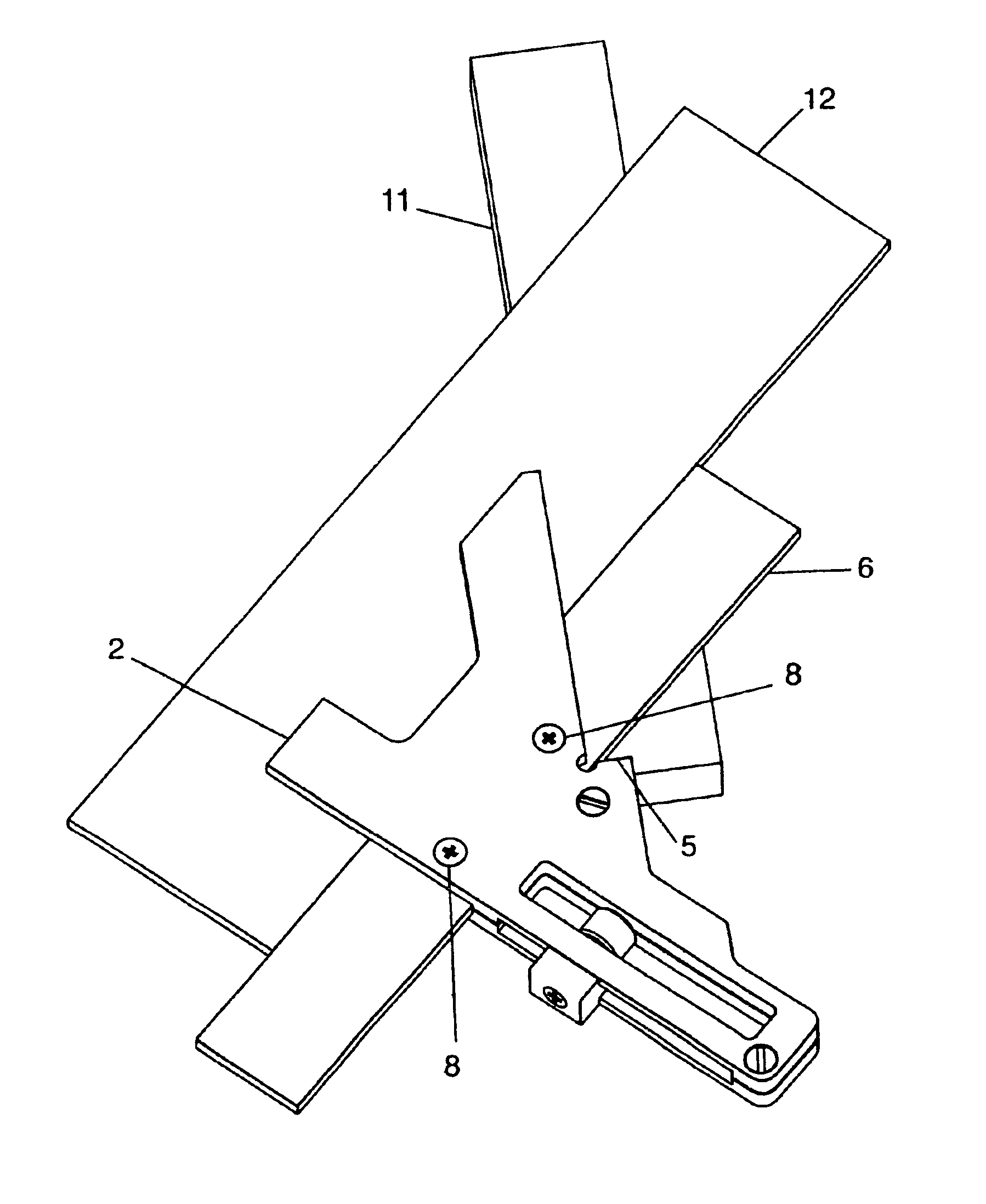
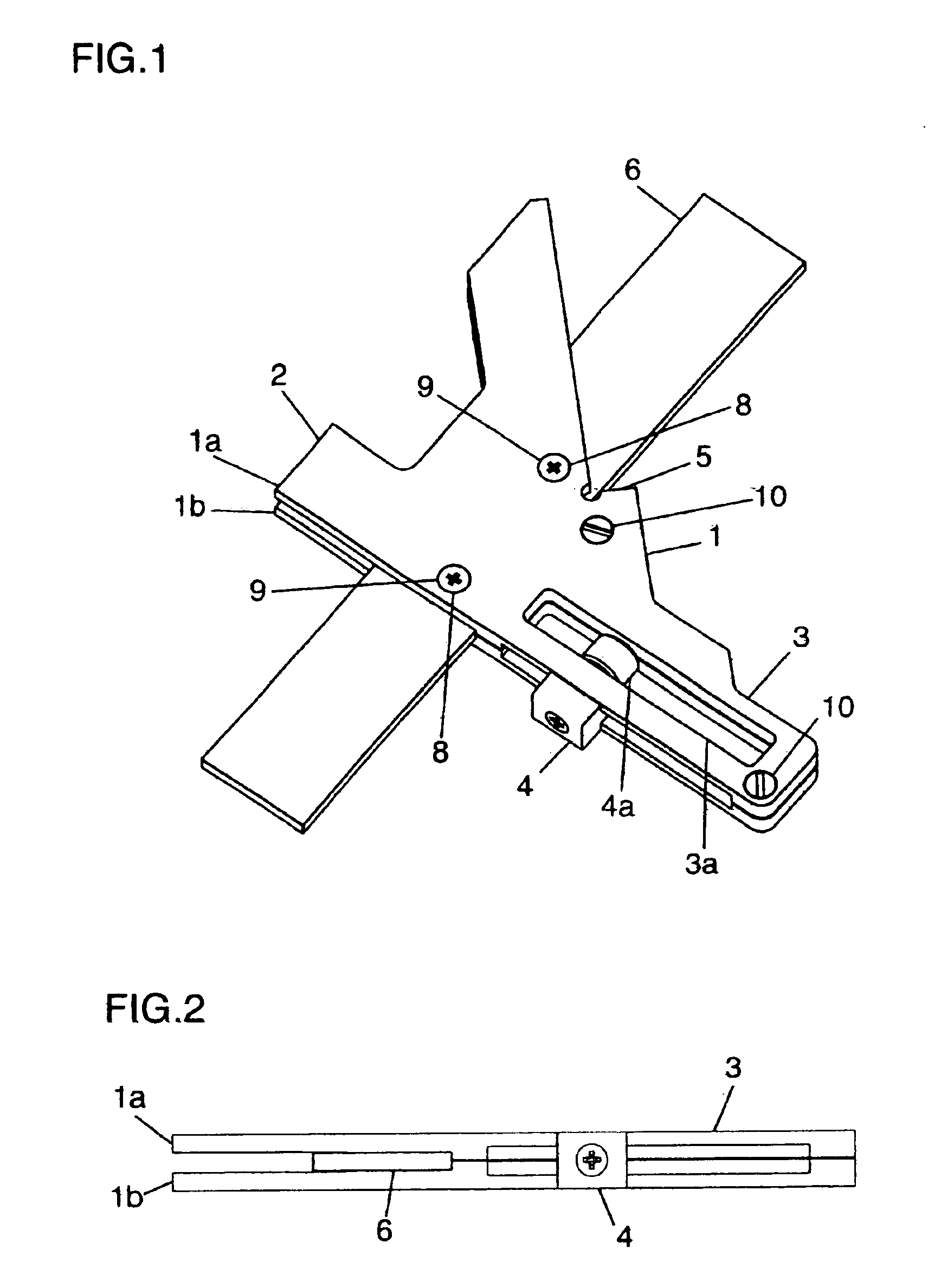
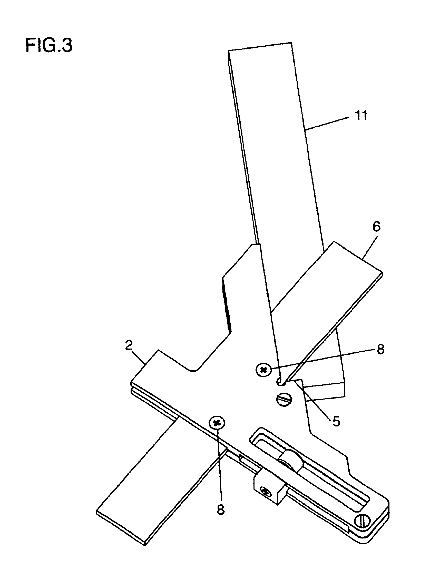
[0021]In FIG. 1, one embodiment of the jig is shown in which 1 denotes a frame, the frame 1 consisting of a top portion 1a and a bottom portion 1b, 2 denotes a yoke portion of the frame (better viewed in FIG. 2), 2a being a removable portion of the frame, 3 is a guide portion of the frame with 3a being a guide way for a movable stopper 4. A locking member 4a is provided in the movable stopper 4 so that the movable stopper may be locked in any position along the guide way 3a. On the opposite side of the guide portion a fixed stopper 5 is formed. An offset blade 6 is comprised of a suitably trimmable material such as plastic with a pair of guide holes 6a, 6a (as shown in FIG. 7) for fixing the guide member in the yoke. A pair of guide pins 8, 8 appropriately spaced from each other are provided in a pair of guide holes 9, 9 opened in the yo...


PUM

PropertyMeasurementUnit
angleaaaaaaaaaa
angleaaaaaaaaaa
angleaaaaaaaaaa

Abstract

A guide device for cutting lap joints includes a frame and a rectilinear guide member, the frame having a Y-like shape and consisting of a removable top portion and a bottom portion forming a yoke therebetween at the upper portion of the Y-like frame. The lower portion of the Y-like frame has a guide portion and one side of the guide portion extends to be co-linear with one side of the yoke portion forming a first adjustable guide surface. The guide portion is provided with a guide way running longitudinally along the guide portion with a movable stopper provided so as to move along the guide surface as guided by the guide way. The movable stopper has a lockable member for locking the movable stopper in any desired position along said guide surface. The other side of the guide portion opposite to the guide surface forms an angle of 45 degrees with another contiguous side of the yoke portion and a fixed stopper is formed near the junction of the yoke portion and this other side of the guide portion. The rectilinear guide member is removably inserted within the yoke, extending perpendicular to the adjustable guide surface, a bottom edge thereof forming a 45 degree angle with said fixed stopper.

Description

BACKGROUND OF THE INVENTION[0001]1. Field of the Invention[0002]This invention relates to novel guide device for cutting lap joints with a router or laminate trimmer, and more particularly to a lap joint jig by which lap joints can be easily cut with exceptional accuracy in a very short time. The jig enables hobbyists to produce professional looking lap joints without the need for various templates, fences, or complicated procedures. The present jig also allows a number of lap joints to be produced continuously so that a number of framing projects, etc. can be accomplished on a scale approaching mass production.[0003]2. Description of the Related Art[0004]Miter joints, as represented in FIG. 8, are one method of making rectangular frames, etc., but they are difficult to make accurately, even more difficult to make visually attractive and tend to be relatively weak. As an alternative, lap joints are a professional method of producing frames for pictures, doors, etc., by which the end...

Claims


Application Information

Patent Timeline
Patent Type & Authority Patents(United States)
IPC IPC(8): B27F1/00
CPCB27F1/00Y10T83/869
Inventor SUGITA, TOYOHISA
Owner SUGITA TOYOHISA
Why Eureka
Eureka Blog
Learn More