Method of producing optical fiber positioning component, and optical fiber positioning component

一种定位器、光纤的技术,应用在光波导的耦合、光导、光学等方向,能够解决引线位置偏移等问题,达到准确形成的效果

Inactive Publication Date: 2008-05-28
SUMITOMO ELECTRIC IND LTD
View PDF2 Cites 0 Cited by
  • Summary
  • Abstract
  • Description
  • Claims
  • Application Information

AI Technical Summary

Problems solved by technology

Therefore, it may happen that when the lead frame 116 is inserted into the end face, the very fine lead 116a may be bent to cause a positional deviation

Method used


Image

  • Method of producing optical fiber positioning component, and optical fiber positioning component
  • Method of producing optical fiber positioning component, and optical fiber positioning component
  • Method of producing optical fiber positioning component, and optical fiber positioning component

Examples


Embodiment Construction

[0039]Hereinafter, a first embodiment of the present invention will be described in detail with reference to the accompanying drawings.

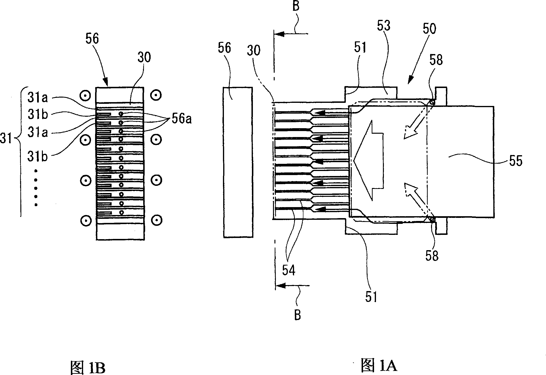
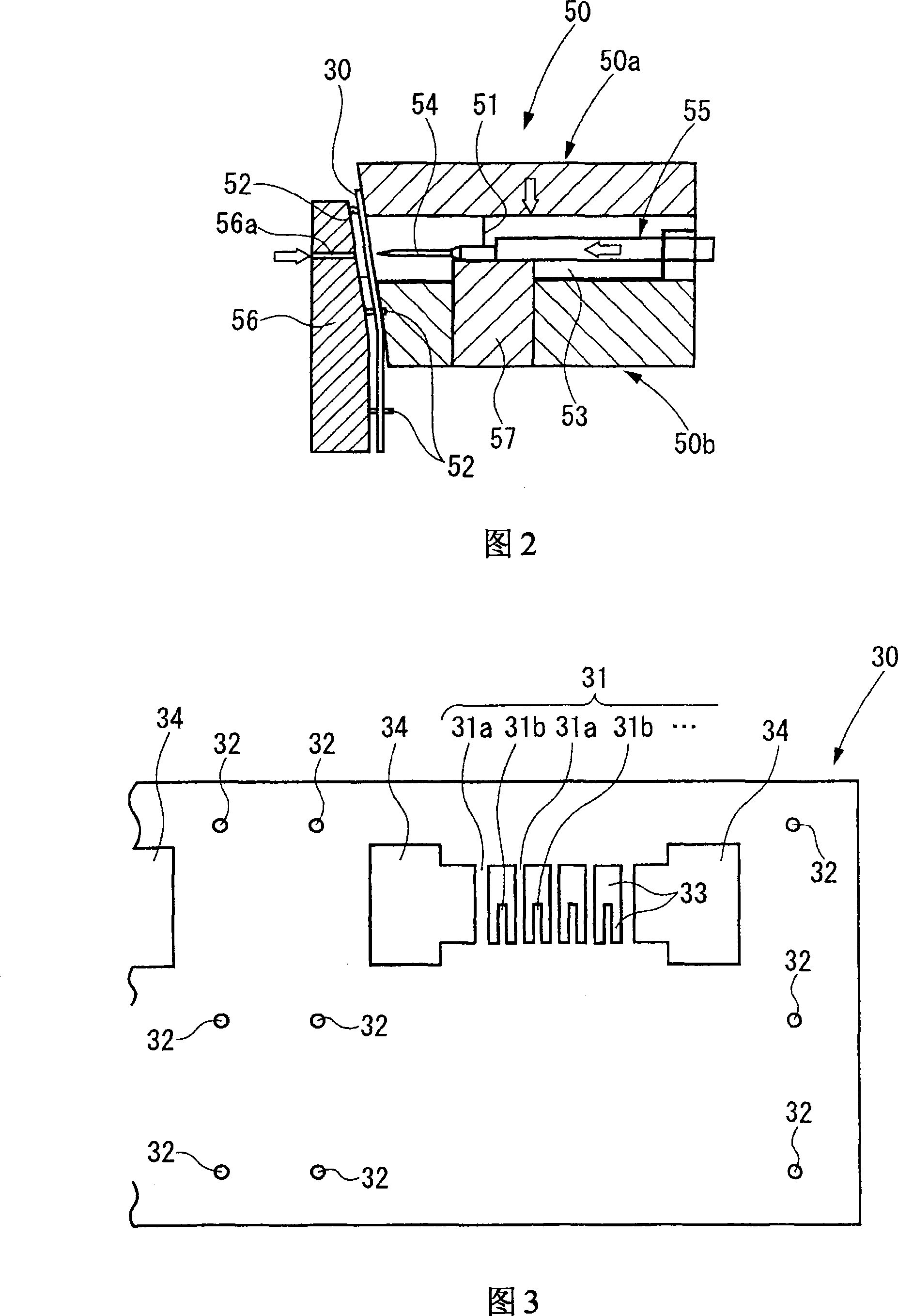
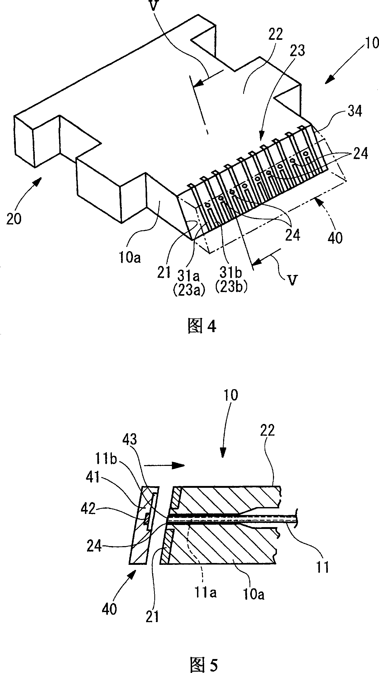
[0040] FIG. 1A is a plan view showing a first embodiment related to a method of manufacturing an optical fiber positioner according to the present invention. FIG. 1B is a cross-sectional view taken along line B-B in FIG. 1A. 2 is a sectional view showing an example of a mold used in the method of manufacturing an optical fiber positioner according to the present invention. FIG. 3 is a plan view showing an example of a lead frame. Fig. 4 is a perspective view showing an example of a fiber positioner. FIG. 5 is a cross-sectional view taken along line V-V in FIG. 4 .

[0041] As shown in FIGS. 1A and 1B , the method of manufacturing an optical fiber positioner, that is, the first embodiment of the present invention is a method of manufacturing an optical fiber positioner 10 (see FIG. 4 ), in which a lead frame 30 (see FIG. 3 ) That is, the ...


PUM


Abstract

A flow of a resin which is injected for insert-molding a wiring plate into an end face of an optical fiber positioning component is regulated by regulating portions disposed in side portions of a die. Therefore, leads of the wiring plate can be prevented from being fixed while remaining to be positionally displaced by the force of the flowing resin. As a result, three-dimensional electrical wirings can be formed easily and correctly.

Description

technical field [0001] The invention relates to a method for manufacturing an optical fiber positioner for connecting an optical fiber and a photoelectric conversion unit. More particularly, the present invention relates to a method of manufacturing an optical fiber positioner for connecting a plurality of optical fibers passing through a through hole provided in a molded part to a The photoelectric conversion unit opposite to the through hole. Background technique [0002] With the development of broadband, there is an increasing demand for increased speed and capacity in network node routers and information home appliances. In order to comply with this development, research is being carried out to introduce optical interconnection, which uses the broadband characteristics of optical fiber to perform E / O conversion in the input / output part of electrical transmission to implement high-speed and large-capacity transmission. Therefore, a technique for connecting photoelectri...

Claims


Application Information

Patent Timeline
Patent Type & Authority Applications(China)
IPC IPC(8): G02B6/42
CPCG02B6/3817G02B6/3652G02B6/3696G02B6/4219G02B6/3878G02B6/4249G02B6/40
Inventor 樱井涉田村充章古山英人滨崎浩史沼田英夫
Owner SUMITOMO ELECTRIC IND LTD
Why Eureka
Try Eureka