Electronic prototyping enclosure

a prototyping enclosure and electronic technology, applied in the direction of electrical apparatus, coupling device connection, electrical apparatus casing/cabinet/drawer, etc., can solve the problems of inferior appearance of the prototype device, difficult and sometimes impossible processes, and easy cracking of plastic panels in drilling, sawing and cutting processes, etc., to achieve accurate and convenient formation

Inactive Publication Date: 2011-08-02
CHAN ERIC K D
View PDF6 Cites 0 Cited by
  • Summary
  • Abstract
  • Description
  • Claims
  • Application Information

AI Technical Summary

Benefits of technology

It is a principal object of the present invention to provide a protective box for fabricating a prototype electrical and electronic device in which openings can be accurately and readily formed without the use of powered tools.
It is another object of the present invention to provide a protective box for fabricating a prototype electrical and electronic device in which electrical components may be securely and readily located therein with a minimum number of electrical wiring connections.
It is another object of the present invention to provide a protective box for fabricating a prototype electrical and electronic device having a clear plastic top panel made of a plastic material in which openings of selected shaped can easily be formed with a puncher.
It is still another object of the present invention to provide a protective box for fabricating a prototype electrical and electronic device in which openings and labeling may be formed accurately and easily.

Problems solved by technology

It has been very problematic in forming such openings in the various side, top and bottom panels of the plastic box since these openings are formed commonly by drilling, sawing, and cutting the plastic panels at the required locations; and the plastic panels can easily break or crack in the drilling, sawing and cutting processes.
It is particularly problematic to carry out these processes with a relatively small size plastic box for use in enclosing a relatively small circuit design, because of the difficulties in retaining and mounting the small plastic box securely during the sawing, cutting and drilling processes.
These processes are difficult and sometimes impossible to carry out due to the restricted space available for inserting the drill and / or the cutting tool inside a relatively small box.
Often the filing process would result in a rather ugly irregularly shaped opening which ultimately renders an inferior appearance in the prototype device.
It is extremely difficult to determine and to mark on the top panel of the plastic box accurately at the exact locations for forming the openings for accommodating the rotary shaft and slidable handle of these control and display electrical components.
Such operation markings are also difficult to provide on the plastic surface.
Since an adhesive label can easily fall off due to the deterioration of the adhesive or it may be defaced, while inscriptions of markings are difficult and time consuming to make, or to engrave neatly on the plastic surface.
Also, due to the limited space available in the protective plastic box, many electrical components such as connectors, switches, connection jacks, are necessarily located along the narrow space between the printed circuit board and the side panels inside the box, and a plurality of electrical wiring must be employed for directly connecting between the connection terminals of these electrical components and the printed circuit board.
The plurality of electrical wiring connections are time consuming to make, and the connections are unreliable due to the tendency of damaging the wiring or shorting of the connection terminals.

Method used


Image

  • Electronic prototyping enclosure
  • Electronic prototyping enclosure
  • Electronic prototyping enclosure

Examples


Embodiment Construction

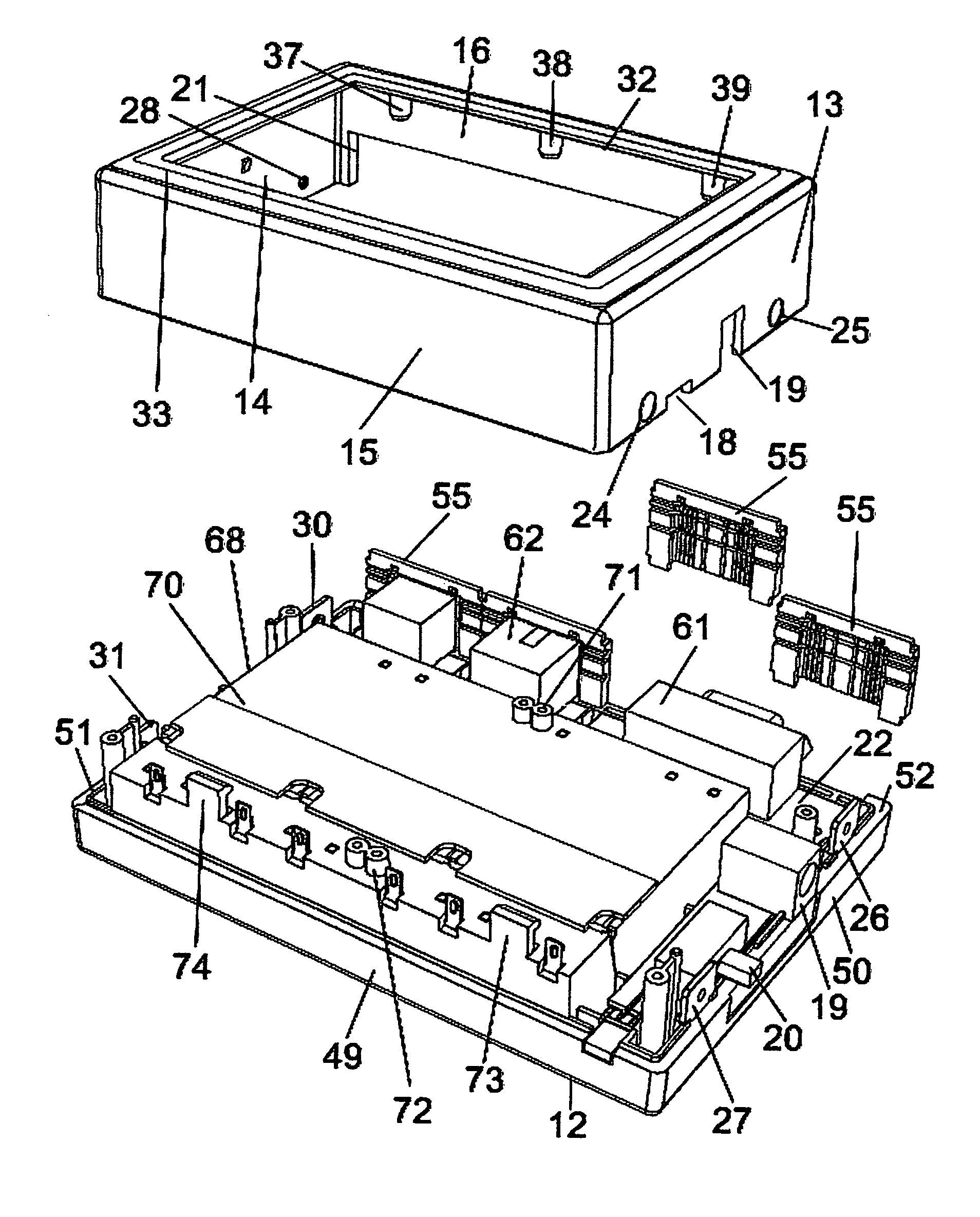
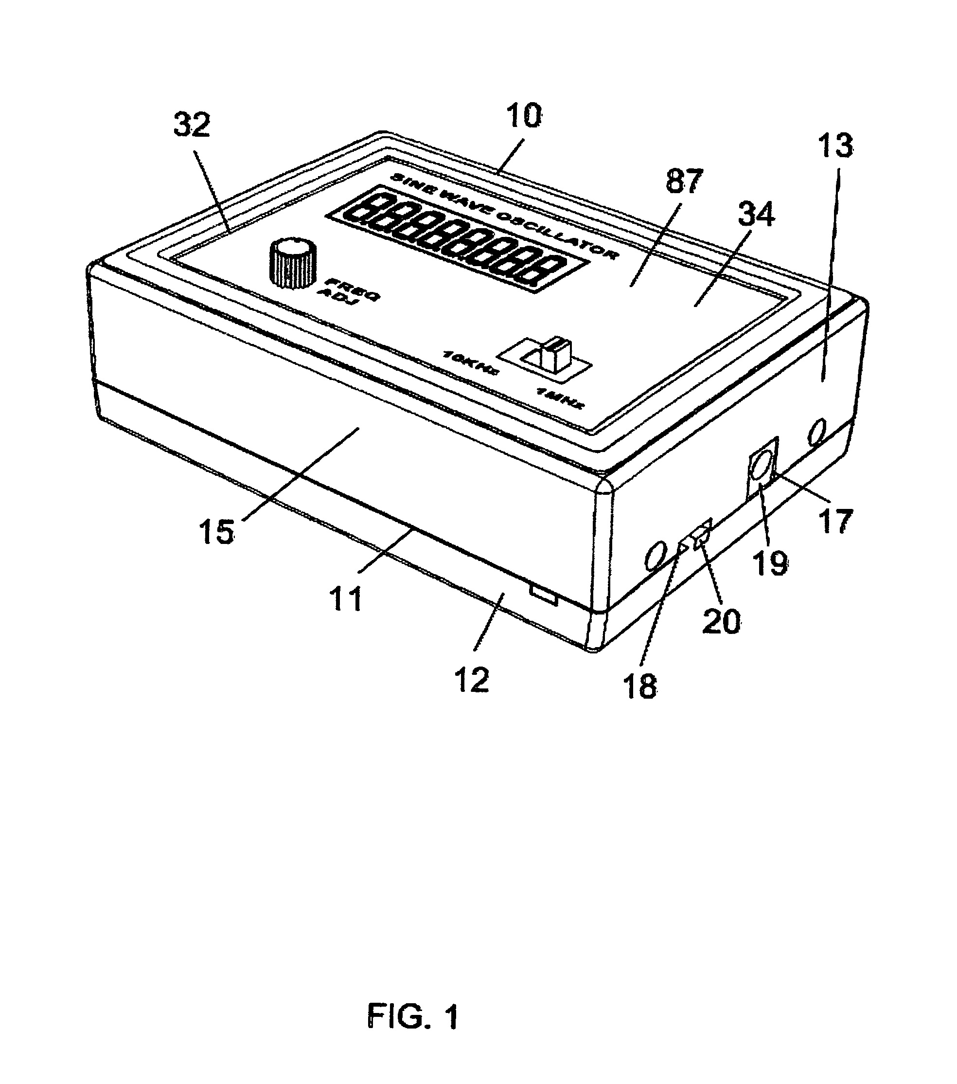
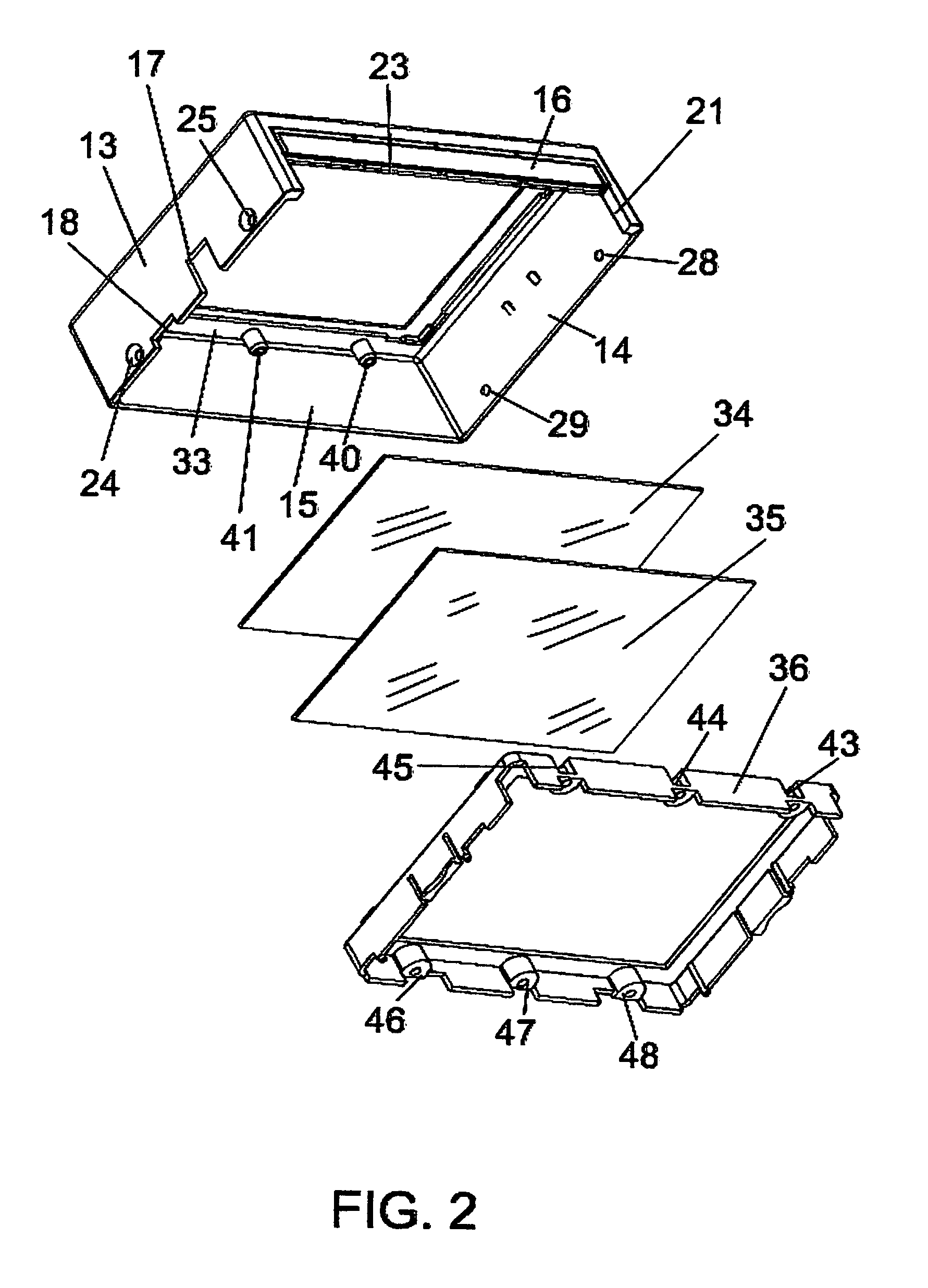
With reference to the drawings in which like reference numerals in the various views designate corresponding parts, the enclosure 10 of the present invention, consists of a top cover casing 11 and a lower support base 12 which are engageable with one another to form the enclosure 10. The top cover casing 11 has downwardly extending skirting side walls 13, 14, 15, and 16. The side wall 13 may be provided with pre-formed cut-outs 17 and 18 for accommodating electrical components such as connection socket 19 and a power switch 20 mounted in the right edge area of the lower support base 12. An elongated cut-out 21 is formed in the lower portion of the side wall 16 in order that electrical components may be located in the edge area 22 in the lower support base 12. A groove 23 is formed in the lower edge of the side wall 16. Mounting openings 24 and 25 may also be formed in the right side wall 13 for receiving mounting screws (not shown) for securing the top cover casing 11 to the lower s...


PUM


Abstract

The protective electronic prototyping enclosure is conveniently formed to accommodate various prototype electronic projects. Openings in the enclosure may be accurately formed and markings can be neatly and precisely formed by on a paper label printed by using the computer. Variable panels are provided for covering spaces between electrical components located adjacent to the side panels of the enclosure.

Description

BACKGROUND OF THE INVENTION1. Field of the InventionThis invention relates to an enclosure for constructing prototype electrical and electronic devices.2. Background ArtIn the design of electrical and electronic circuits, particularly for circuit developers and students, commonly after the circuit design has been established, a prototype is built to test the operation and feasibility of the circuit design. The prototype not only must be functional to provide the required purposes, it must also be able to withstand various inadvertent mishaps in its handling during its construction with various electrical components, and changes of electrical components which may be required during its testing stage, as well as when submitting the prototype for evaluation by other people. In order to preserve the integrity of the circuit design, a secure protective project enclosure must be provided. Heretofore, rectangular plastic boxes are employed for fabricating prototype electrical and electroni...

Claims


Application Information

Patent Timeline
Patent Type & Authority Patents(United States)
IPC IPC(8): H01R13/502
CPCH05K5/00
Inventor CHAN, ERIC K. D.
Owner CHAN ERIC K D
Why Eureka
Try Eureka