Coil support structure and magnetic disk drive

a support structure and magnetic disk drive technology, applied in the direction of magnetic recording, data recording, instruments, etc., can solve the problems of affecting the accuracy of the carriage, and affecting the operation of the carriage, etc., to achieve accurate and easy formation, space is at a premium

Inactive Publication Date: 2011-10-04
WESTERN DIGITAL TECH INC
View PDF16 Cites 0 Cited by
  • Summary
  • Abstract
  • Description
  • Claims
  • Application Information

AI Technical Summary

Benefits of technology

According to an aspect of the present invention, the outer holding portion includes a reinforcement portion formed thereon for covering part of a transverse end face of the coil exposed. This eliminates the possibility of the outer holding portion's being separated from the coil and damaged. If there is no pronounced orientation in a direction, in which the outer holding portion comes off the coil, or if there is further reduction in strength of the carriage housing due to further promotion toward thinner devices, the carriage housing may be reinforced by providing reinforcement portions so that the portions may cover part of the transverse end faces on both the front side and the backside, respectively. The reinforcement portion may cover the entire surface of the transverse end face of the coil. It is nonetheless preferable that the reinforcement portion cover only partly if there is no extra space between the coil and a voice coil magnet or a voice coil yoke.
The reinforcement portion may be accurately and easily formed if a corresponding shape is formed in a plastic mold and the portion is injection-molded integrally with the carriage housing and the coil. The number of turns in a layer of the coil in contact with the outer holding portion may be selected to form a step between layers of the coil. Depending on the embodiment of the step, the outer holding portion may be oriented toward a direction of its being damaged in a lateral direction of the coil. The step may be formed between an outermost peripheral layer of the coil and a layer adjacent thereto and inner therefrom by reducing the number of turns in the outermost peripheral layer from that in an innermost peripheral layer of the coil. In this case, the number of conductive wires for the outermost peripheral layer should selected so as to fall within a range of about 40% to 60% of the number of conductive wires of the layer adjacent to and inner from the outermost peripheral layer and the conductive wire be wound in alignment with each other from either one of the transverse end faces of the coil. By so doing, the step may give the outermost peripheral layer a strength that is sufficient to oppose an external force in the lateral direction.
As a result, the outer holding portion tends to be damaged in a direction from a higher end of the step toward a lower end thereof. If the step is formed by means of the layers of the coil and the outer holding portion is thereby oriented toward the direction of its being easily damaged as described above, it becomes necessary for the reinforcement portion to cover part of only the transverse end face of the coil disposed in the higher end of the step. Adopting this structure allows the reinforcement portion to be provided only on one side, either the front side or the backside, in order to reinforce the carriage housing. The structure is therefore particularly advantageous in a compact magnetic disk drive, in which space is at a premium. The step formed in the layer of the coil in contact with the outer holding portion is not limited to the arrangement, in which the step is formed between the outermost peripheral layer and the layer adjacent thereto and immediately inner therefrom. Rather, the steps may be formed in a plurality of layers inner from the outermost peripheral layer.
In accordance with a second aspect of the present invention, the method of winding the conductive wire for the outermost peripheral layer of the coil is devised so as to prevent the outer holding portion from being deviated from the outer end face. A step may be formed in the layer of the coil in contact with the outer holding portion so as to prevent the outer holding portion from coming off from the coil in both directions toward the front side and the backside. The carriage housing may thereby be reinforced even without using any reinforcement portion. Forming steps in both directions leaves aligned windings of the conductive wire only at a central portion of the outermost peripheral layer. Alternatively, the aligned windings of the conductive wire may be provided on both sides with none at the central portion of the outermost peripheral layer. Alternatively, the conductive wire in contact with the outer holding portion may still be wound with a spacing interposed between two adjoining turns, instead of using the aligned winding, thereby forming steps in two directions. Still alternatively, the number of turns of each layer is reduced gradually toward the outermost peripheral layer to form steps in a pyramid form.

Problems solved by technology

A mechanical stress is thus applied to the carriage assembly and there is a good likelihood that the synthetic resin surrounding the voice coil will be damaged.
The mechanical stress may, instead, lead to a functional fault during operation of the carriage.
A major cause of the damaged carriage housing is the carriage housing that has been made thinner.
It has been found that, in such a support structure as that described above, it is likely that the outer holding portion 3 will be deviated in a direction of a lower step as indicated by an arrow 10 in FIG. 7(B) and thereby damaged through human or mechanical handling during a manufacturing process.

Method used


Image

  • Coil support structure and magnetic disk drive
  • Coil support structure and magnetic disk drive
  • Coil support structure and magnetic disk drive

Examples


Embodiment Construction

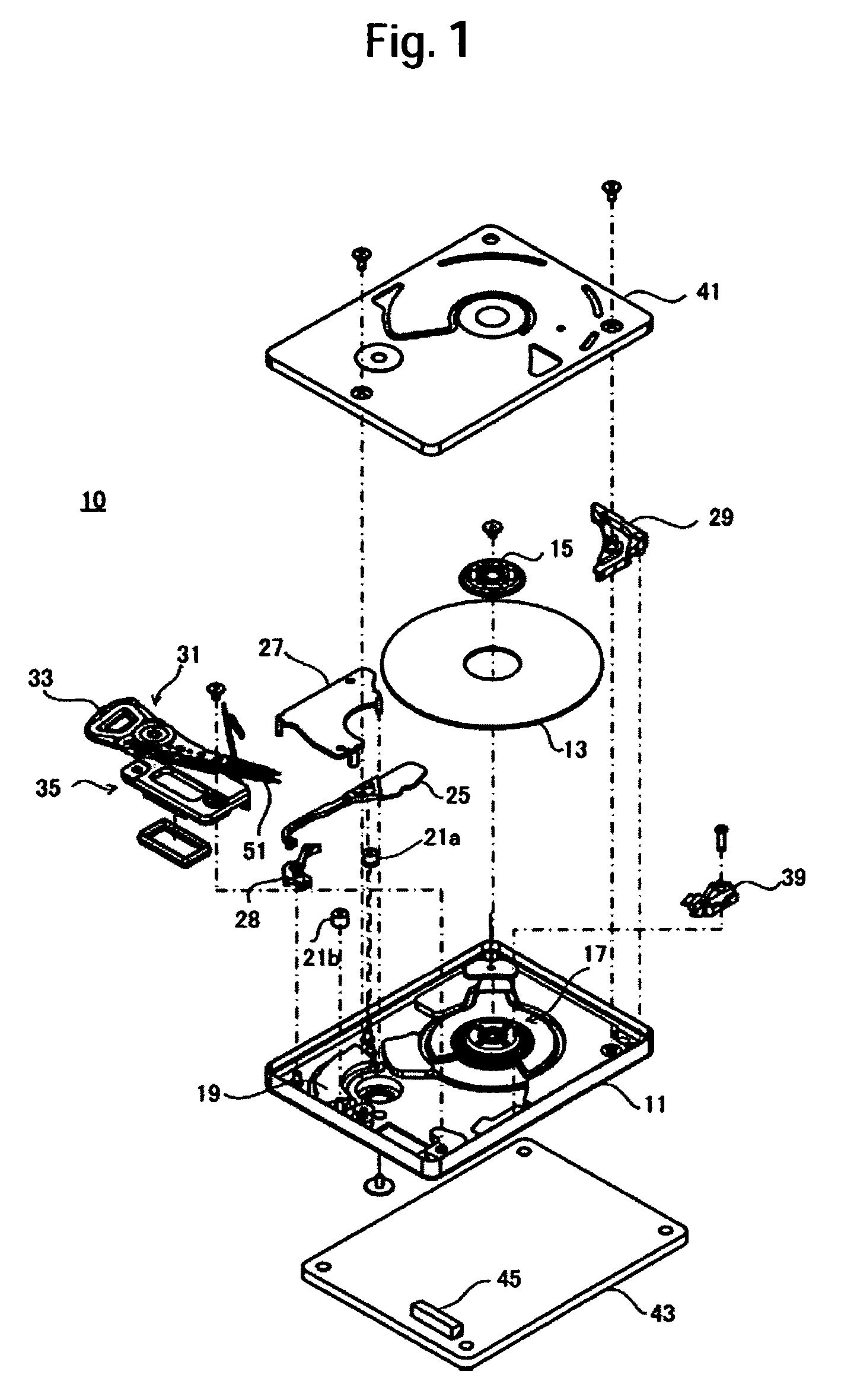
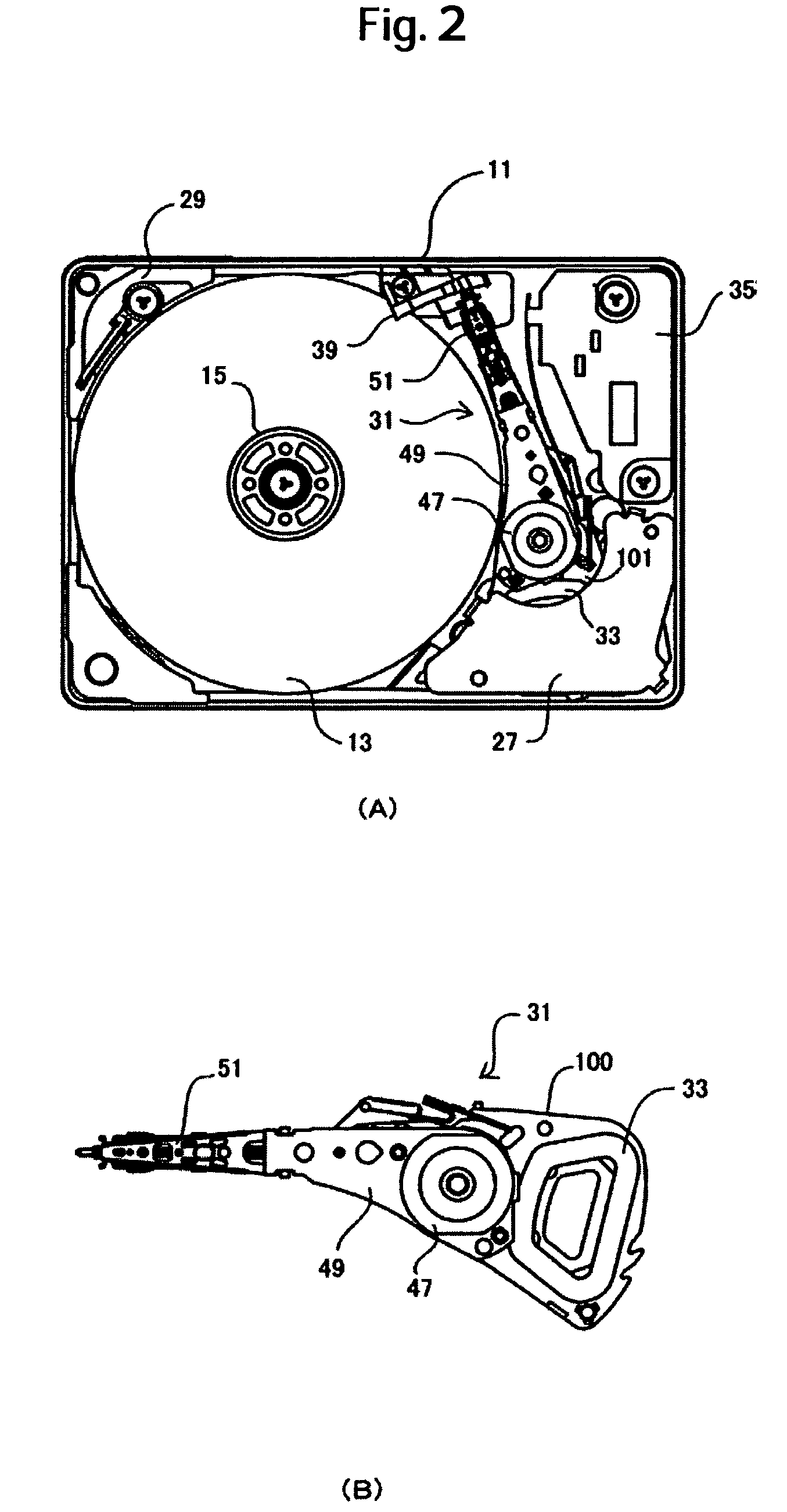
FIG. 1 is an exploded perspective view showing a magnetic disk drive according to an embodiment of the present invention. FIG. 2(A) is a plan view showing the magnetic disk drive with a base cover removed. FIG. 2(B) is a plan view showing an actuator assembly. A magnetic disk drive 10 may be a compact magnetic disk drive that handles a magnetic disk having a diameter of 1″ (25 mm) or less. The magnetic disk drive 10 includes a base 11, on which a spindle motor 17 and a voice coil magnet 19 are mounted. A magnetic disk 13 is secured to a spindle shaft of the spindle motor 17 with a clamp 15. Mounted on the base 11 are a circulation filter block 29, a ramp mechanism 39, a latch mechanism including a long lever 25 and a short lever 28, crash stops 21a, 21b, and a voice coil yoke 27.

In addition, an actuator assembly 31 is mounted rotatably about a pivot assembly 47 on the base 11. The actuator assembly 31 includes a carriage assembly 100, an actuator arm 49, an HGA 51, and the pivot ass...


PUM

PropertyMeasurementUnit
diameteraaaaaaaaaa
conductiveaaaaaaaaaa
structureaaaaaaaaaa

Abstract

A voice coil includes a stack of a plurality of layers of aligned windings held between an outer holding portion and an inner holding portion of the carriage assembly. The carriage assembly is formed integrally with the voice coil through injection molding. An outermost peripheral layer is a conductive wire wound a number of turns that falls short of the number of turns required to constitute a complete layer. A step is thereby formed between the outermost peripheral layer and a layer adjacent thereto and inner therefrom. The outer holding portion includes a reinforcement portion formed thereon to cover part of a transverse end face of the voice coil. The outermost peripheral layer opposes a force acting on the outer holding portion from top downward and the reinforcement portion opposes a force acting on the outer holding portion from bottom upward.

Description

CROSS-REFERENCES TO RELATED APPLICATIONSThis application claims priority from Japanese Patent Application No. JP2005-300978, filed Oct. 14, 2005, the entire disclosure of which is incorporated herein by reference.BACKGROUND OF THE INVENTIONThe present invention relates generally to a support structure for a coil mounted in a carriage of a magnetic disk drive or the like and, more particularly, to a support structure for reinforcing a thin carriage that is injection-molded integrally with a coil.In magnetic disk drives, an actuator mounted with a voice coil is rotated to position a magnetic head to a predetermined position. The voice coil constitutes, with a voice coil magnet and voice coil yoke mounted on a base, a voice coil motor (VCM). A carriage assembly includes a carriage housing and the voice coil. The carriage housing includes a pivot hole, in which a pivot assembly is mounted, a mounting portion of a head gimbal assembly (HGA), and a holding portion of the voice coil.In a r...

Claims


Application Information

Patent Timeline
Patent Type & Authority Patents(United States)
IPC IPC(8): G11B21/02
CPCG11B5/54G11B5/5521
Inventor MATSUMURA, SATOSHIMORI, HIDEKIDEGUCHI, TAKAAKIMATSUDA, HIROSHI
Owner WESTERN DIGITAL TECH INC
Why Eureka
Try Eureka