
Log home construction system

a construction system and log structure technology, applied in the field of structures, can solve the problems of undesirable maintenance burden, gaps or cracks in the log structure, etc., and achieve the effect of facilitating the attachment of the rod

Inactive Publication Date: 2005-06-14
HERITAGE LOG HOMES
View PDF20 Cites 65 Cited by
  • Summary
  • Abstract
  • Description
  • Claims
  • Application Information

AI Technical Summary

Benefits of technology

[0008]In a different embodiment, the wall comprises a plurality of wall members stacked substantially vertically, including a bottom wall member and a top wall member. Each of the wall members include an upper surface in opposed relation to a lower surface and a through opening extending from the upper surface to the lower surface. A through opening in each wall member is aligned with a through opening in all other wall members so as to form a through opening in the wall extending from the upper surface of the top wall member to the lower surface of the bottom wall member. A rod is positioned in the through opening of the wall, the rod having an upper end in opposed relation to a lower end, and the rod extending along a first axis. A lower fastener is attached to the lower end of the rod and attached to the lower surface of the bottom wall member. The lower fastener comprises a locking nut and the locking nut includes an internally threaded portion for receiving a threaded portion of the lower end of the rod. The threaded portion of the locking nut extends substantially along the first axis and the locking nut has a tapered surface opening at an end of the threaded portion for receiving the rod to facilitate attachment of the rod to the lower fastener. The locking nut also has a flange extending transversely to the first axis for supporting the threaded portion. The flange of the locking nut includes a fastening means attaching the flange to the lower surface of the bottom wall member to secure the lower fastener to the bottom wall member A spring support plate is attached to the upper surface of the top wall member. The spring support plate has an opening for the rod to pass therethrough and the spring support plate also has at least one hole for at least one spring support plate fastener. At least one the spring support plate fastener passes through a hole in the spring support plate thereby attaching the spring support plate to the top wall member. The wall also includes an upper fastener attached to the upper end of the rod adjacent the upper surface of the top wall member and a spring positioned between the upper fastener and the spring support plate for applying a downward force to the top wall member.

Problems solved by technology

Without accommodation for the settling, the log structure may develop gaps or cracks in the walls.
One previous approach has been to periodically tighten a fastener which compresses the wall members, however, this approach creates an undesirable maintenance burden.

Method used


Image

  • Log home construction system
  • Log home construction system
  • Log home construction system

Examples


Embodiment Construction

)

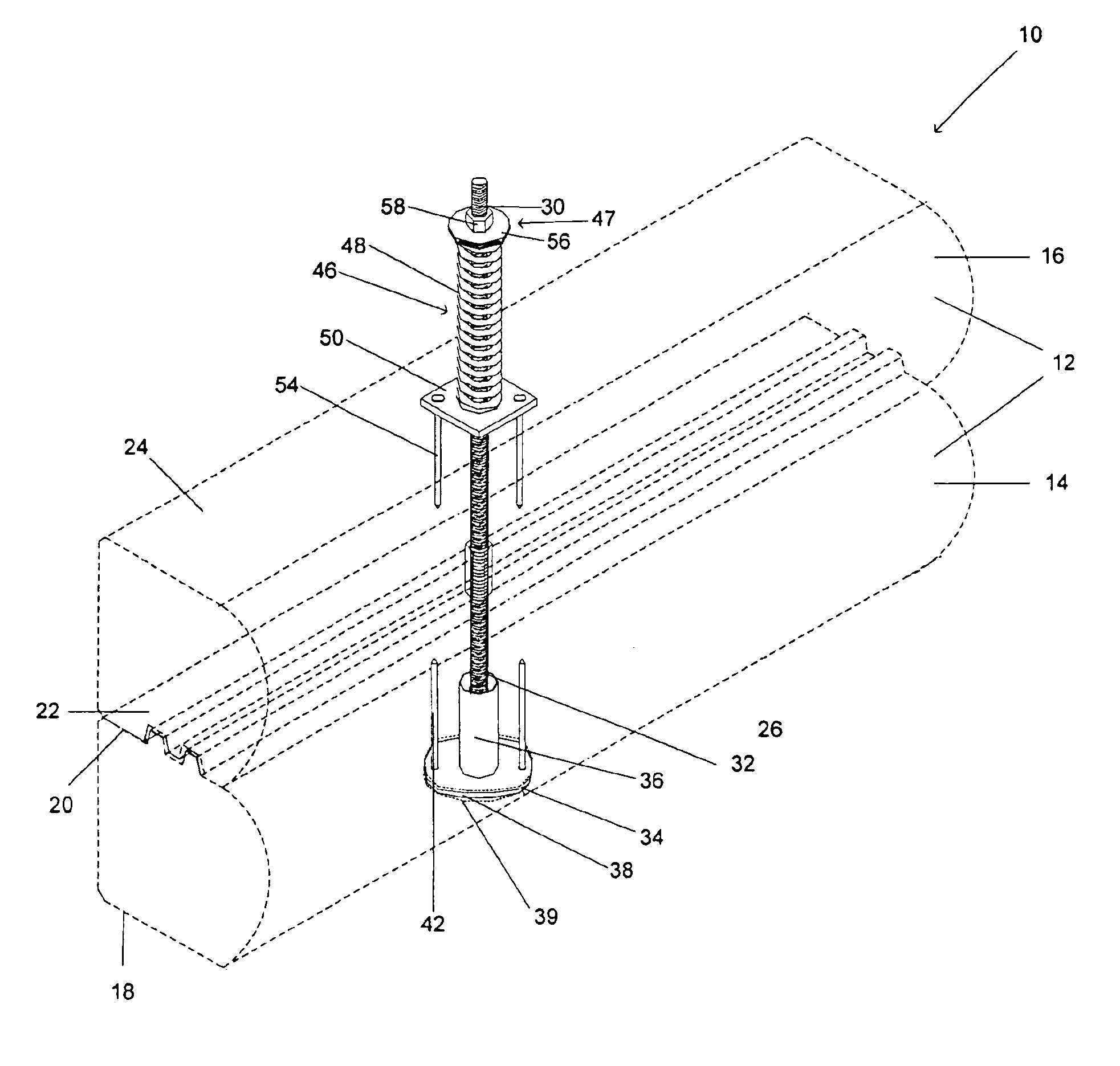
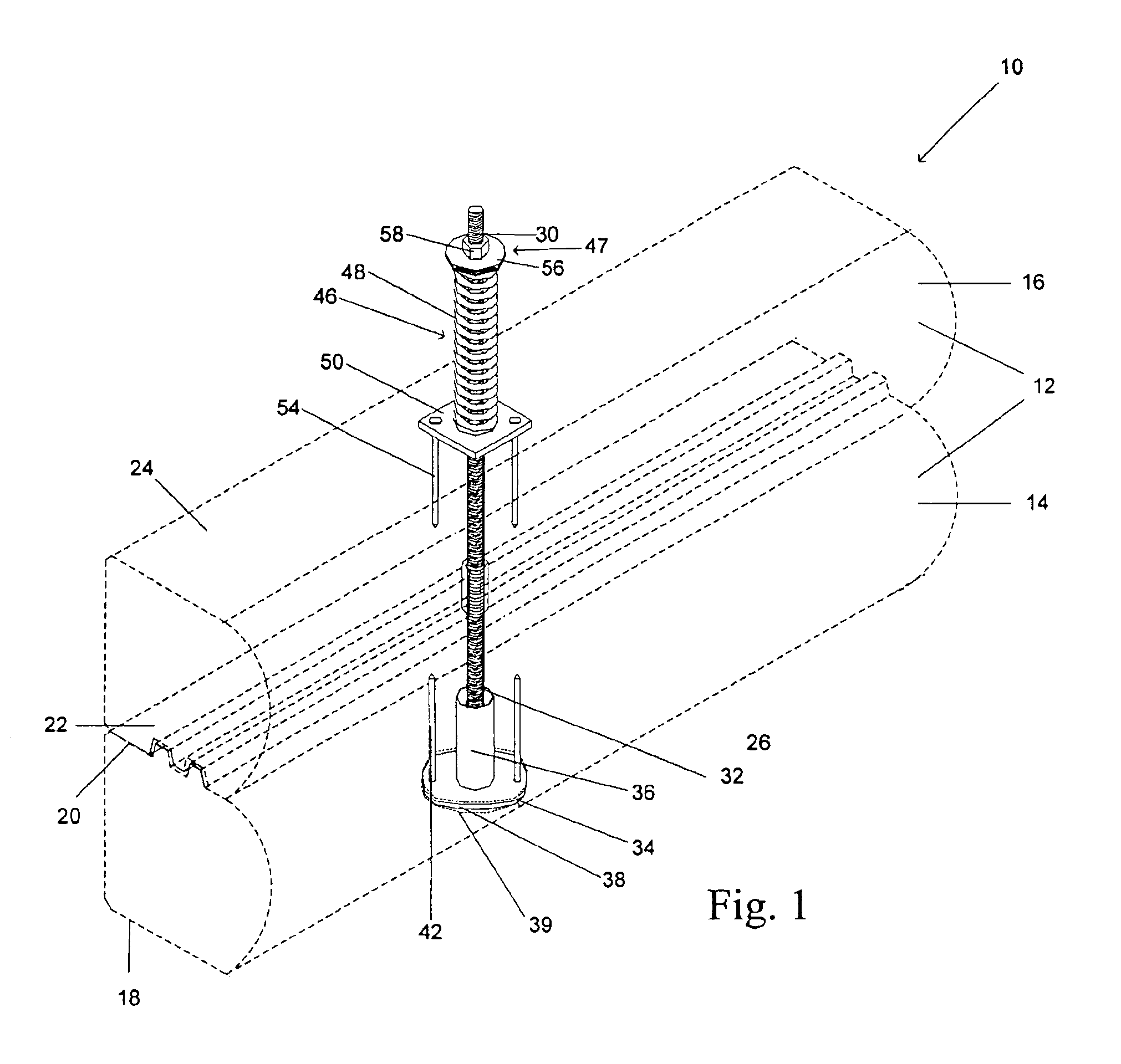
[0015]With reference now to the drawings in which like reference characters designate like or similar parts throughout the several views, FIG. 1 provides a perspective view of a portion of a wall 10 constructed according to the invention. Wall members 12 are preferably stacked substantially vertically. In a particularly preferred embodiment, the wall members 12 comprise wooden logs. The wooden logs may be sawed, cut, formed, or otherwise processed prior to being stacked as part of the wall 10. The wall members 12 can also be formed from other materials such as plastics, resins or other materials suitable for constructing structures. Each wall member 12 includes an upper surface in opposed relation to a lower surface. Preferably, the lower surface of each wall member 12 is substantially parallel to the upper surface of each wall member 12.

[0016]The wall members 12 may be of any suitable cross-sectional shape. Such cross-sectional shapes include, but are not limited to, a substantial...


PUM


Abstract

A wall includes a plurality of wall members stacked substantially vertically and including a bottom wall member and a top wall member. Each wall member has an upper surface in opposed relation to a lower surface and a through opening extending from the upper surface to the lower surface. A through opening in each wall member is aligned with a through opening in all other wall members so as to form a through opening in the wall extending from the upper surface of the top wall member to the lower surface of the bottom wall member. A rod, having an upper end in opposed relation to a lower end, is positioned in the through opening of the wall and a lower fastener attaches to the lower end of the rod adjacent the lower surface of the bottom wall member. An upper fastener attaches to the upper end of the rod adjacent the upper surface of the top wall member, and an actuator is positioned between the upper fastener and the upper surface of the top wall member for applying a downward force to the top wall member.

Description

BACKGROUND[0001]1. Field of the Invention[0002]The present invention relates generally to structures composed of individual wall members and methods of constructing those structures. More particularly, the present invention relates to log structures and a thru-bolt system for constructing log structures.[0003]2. Background of the Invention[0004]Log structures are constructed for a variety of purposes. The log structures typically are comprised of walls which include individual wall members that shrink or settle over time. The shrinkage or settling must be accommodated to facilitate a proper fit between the wall members. Without accommodation for the settling, the log structure may develop gaps or cracks in the walls. One previous approach has been to periodically tighten a fastener which compresses the wall members, however, this approach creates an undesirable maintenance burden.[0005]Therefore, there is a need for an improved wall and method of constructing a wall which simplifies...

Claims


Application Information

Patent Timeline
Patent Type & Authority Patents(United States)
IPC IPC(8): E04B2/70
CPCE04B2/702
Inventor STUTTS, H. CRAIG
Owner HERITAGE LOG HOMES
Features
  • Generate Ideas
  • Intellectual Property
  • Life Sciences
  • Materials
  • Tech Scout
  • Unparalleled Data Quality
  • Higher Quality Content
  • 60% Fewer Hallucinations
Learn More