Structure for dispensing ice in refrigerator

a technology for dispensing structures and refrigerators, which is applied in the direction of ice production, domestic cooling apparatus, lighting and heating apparatus, etc., can solve the problems of inoperable augers, and achieve the effect of preventing malfunctions and effective utilization of freezing chamber spa

Inactive Publication Date: 2005-06-14
LG ELECTRONICS INC
View PDF11 Cites 63 Cited by
  • Summary
  • Abstract
  • Description
  • Claims
  • Application Information

AI Technical Summary

Benefits of technology

[0023]An object of the present invention is to provide a structure for dispensing an ice in a refrigerator, in which an automated ice-making device and an ice bank are installed at a door of a freezing chamber to thereby enable an effective utilization of the freezing chamber space and prevent a malfunction when transferring pieces of ice.

Problems solved by technology

Therefore, there are problems that the automated ice-making chamber 1 occupies a large inner space of the freezing chamber 1.
To this end, if the pieces of ice are not discharged for a long time, the pieces of ice are fixedly attached between the augers, thus causing a problem that the augers do not operate.

Method used


Image

  • Structure for dispensing ice in refrigerator
  • Structure for dispensing ice in refrigerator
  • Structure for dispensing ice in refrigerator

Examples


Embodiment Construction

[0044]Reference will now be made in detail to the preferred embodiments of the present invention, examples of which are illustrated in the accompanying drawings. Wherever possible, the same reference numbers will be used throughout the drawings to refer to the same or like parts.

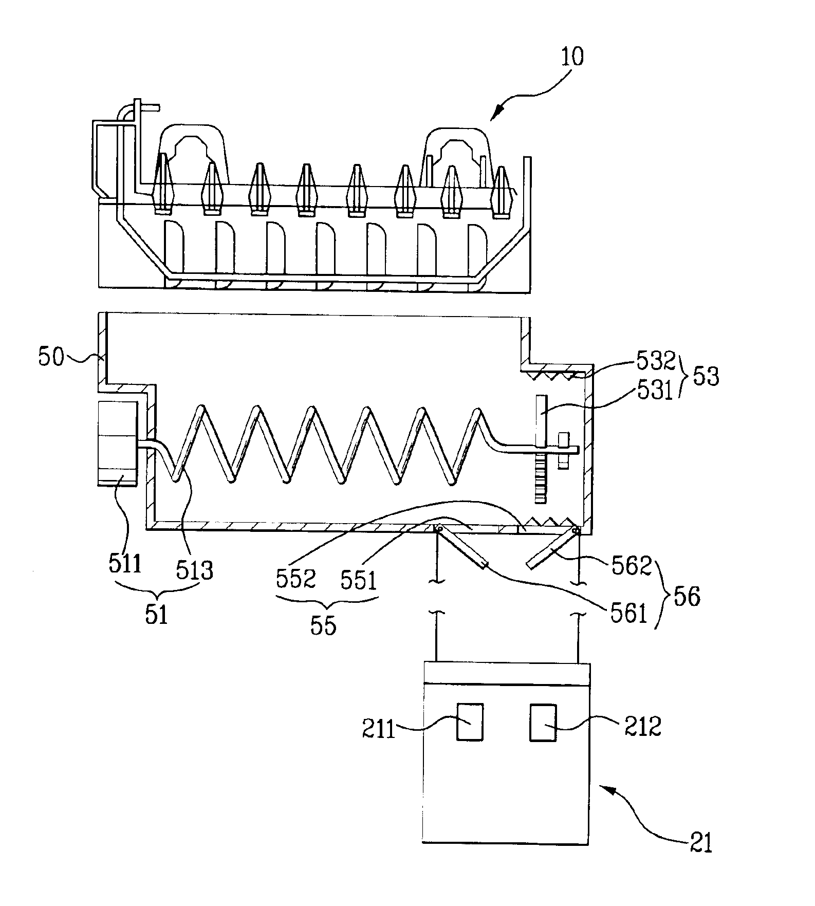
[0045]FIG. 5 is a schematic sectional view of an automated ice-making device 10 and an ice bank 50 in a structure for dispensing pieces of ice in a refrigerator according to the present invention. FIG. 6 is a schematic perspective view of the automated ice-making device and the ice bank 50 according to the present invention. FIG. 7 is a sectional view of an ice bank 500 according to another embodiment of the present invention.

[0046]As shown in FIGS. 5 and 6, the ice bank 50 is installed at a lower portion of the automated ice-making device 10. Since the automated ice-making device 10 is formed at a door 2, water-overflow preventing parts 101 and 102 are formed in order to prevent an overflowing of water in a...


PUM


Abstract

Disclosed is a structure for dispensing ice in a refrigerator, in which an automated ice-making device and an ice bank are installed at a door of a freezing chamber to thereby make its space utilization effectively. The structure of the present invention includes: an ice-making device installed in a door of a freezing chamber; an ice bank storing pieces of ice provided from the ice-making device; an ice transfer unit for transferring the pieces of the ice stored in the ice bank in a width direction; and an ice crushing part for crushing the pieces of the ice transferred by the ice transfer unit.

Description

[0001]This application claims the benefit of the Korean Application No. P2003-0034082 filed on May 28, 2003, which is hereby incorporated by reference.BACKGROUND OF THE INVENTION[0002]1. Field of the Invention[0003]The present invention relates to a structure for dispensing an ice in a refrigerator, and more particularly, to a structure for dispensing an ice in a refrigerator, which includes an automated ice-making device for manufacturing pieces of ice and an ice bank for keeping pieces of ice.[0004]2. Description of the Related Art[0005]In general, a refrigerator is divided into a freezing chamber and a chilling chamber. The chilling chamber is maintained at temperature of 3° C. to 4° C., to keep foods or vegetables in a fresh state. The freezing chamber is maintained at a temperature below 0° C., to keep foods in a frozen state.[0006]Recently, various functions are added to the refrigerator so that a user can use it conveniently. Among them, one function is an automated ice-makin...

Claims


Application Information

Patent Timeline
Patent Type & Authority Patents(United States)
IPC IPC(8): F25C5/04F25C5/00F25C5/18F25C1/24
CPCF25C5/005F25C5/046F25D2400/06F25C2400/10F25C2500/06F25C5/185F25C5/22F25C1/24
Inventor LEE, WOOK YONGOH, SEUNG HWANCHUNG, EUI YEOPLEE, MYUNG RYUL
Owner LG ELECTRONICS INC
Why Eureka
Try Eureka