Printing plate removing/supplying device

a technology for supplying devices and printing plates, which is applied in the directions of pile separation, transportation and packaging, article separation, etc., can solve the problems of increasing the cost of the device, large space needed for the placement of the device, and heavy printing plates, and achieves the effect of less spa

Inactive Publication Date: 2005-06-14
FUJIFILM HLDG CORP +1
View PDF5 Cites 45 Cited by
  • Summary
  • Abstract
  • Description
  • Claims
  • Application Information

AI Technical Summary

Benefits of technology

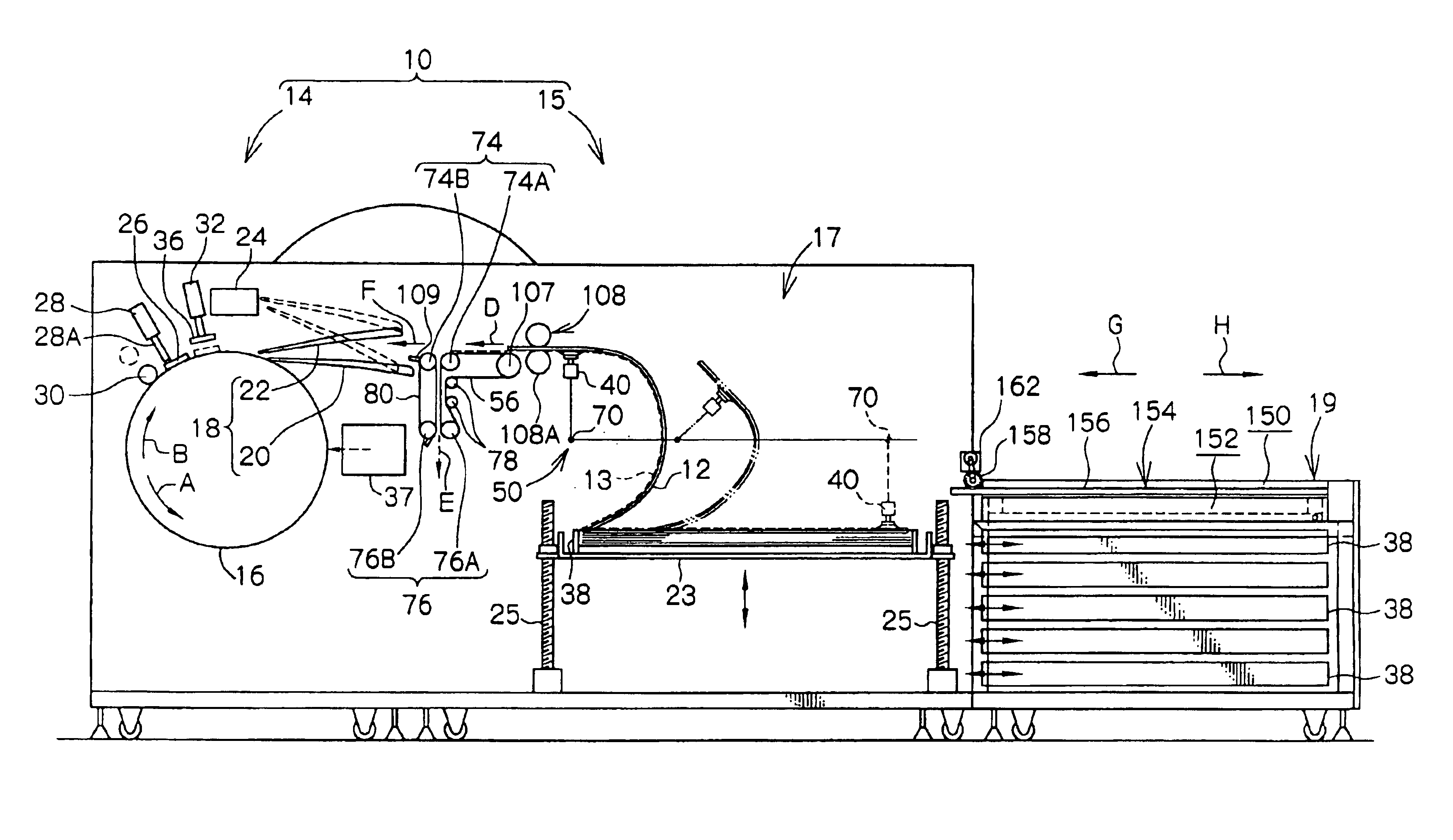
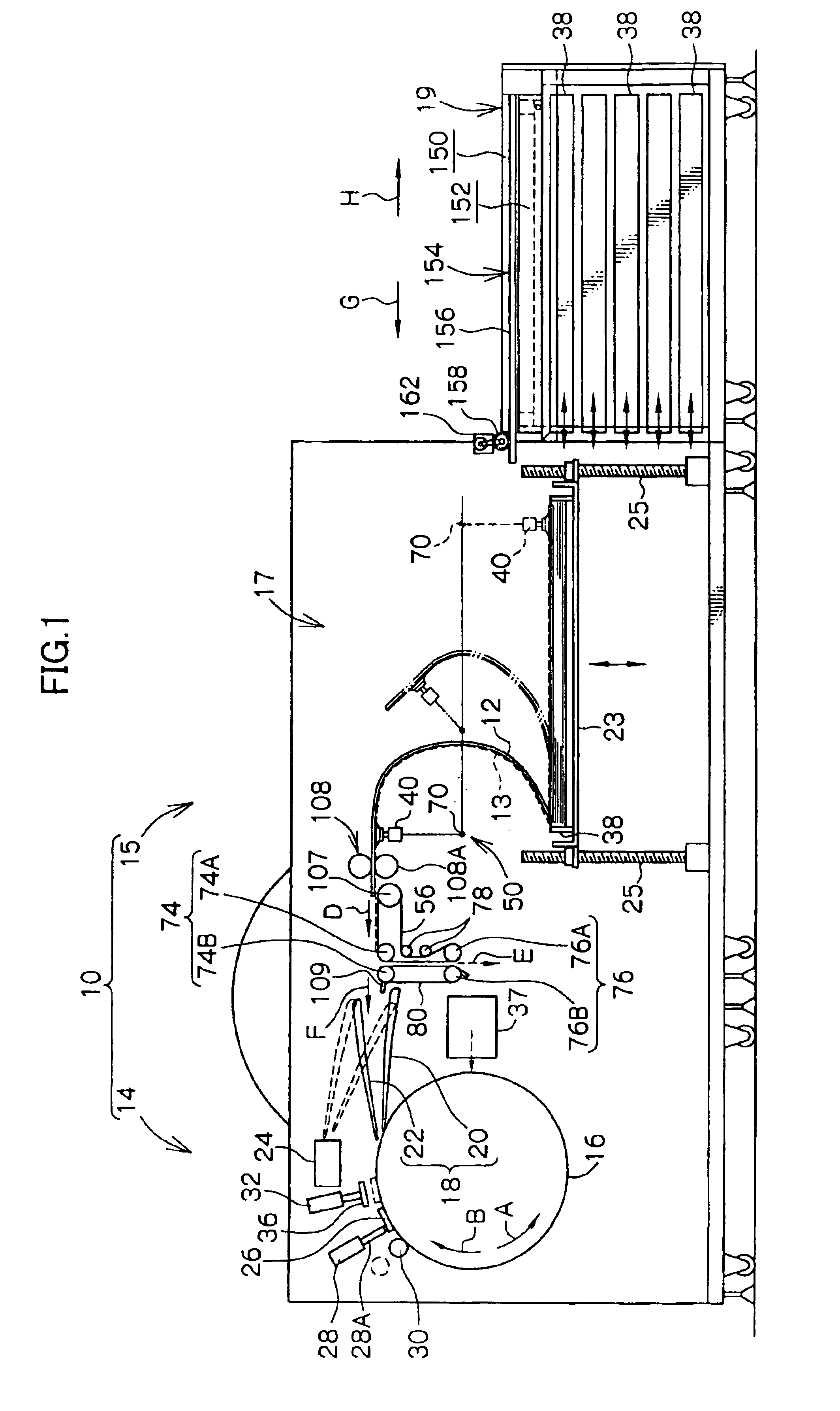
[0012]In view of the aforementioned, an object of the present invention is to provide a printing plate removing / supplying device which results in less space needed for placement of the device, a lowering of the costs of the device, and improved workability at the time of loading printing plates.

Problems solved by technology

A problem arises in that ultimately a large space for placement of the device is needed.
However, the printing plates are heavy.
The rigidity of the side surface covers and the members supporting the side surface covers (hinges or the like) must be made to be high, which results in the cost of the device increasing.
In addition, because the cassettes are accommodated in plural levels in a state in which one is disposed above another, when the device is set such that the height which makes the printing plate loading work easy is the height of the uppermost cassette, a problem arises in that the workability at the time of loading printing plates into the lower cassettes is poor.

Method used


Image

  • Printing plate removing/supplying device
  • Printing plate removing/supplying device
  • Printing plate removing/supplying device

Examples


second embodiment

(Second Embodiment)

[0084]Next, a second embodiment will be described. Structures and operations which are basically the same as those of the above-described first embodiment are denoted by the same reference numerals as in the first embodiment, and description thereof is omitted.

[0085]The structure of a cassette stocker portion 170 serving as an accommodating portion relating to the second embodiment of the present invention is shown in side view in FIG. 3.

[0086]The cassette stocker portion 170 basically has the same structure as that of the cassette stocker portion 19 relating to the above-described first embodiment. However, at the cassette stocker portion 170, the cover member is a shutter 172 which is flexible.

[0087]The end portions of the shutter 172 in the transverse direction thereof (the direction orthogonal to the surface of the drawing of FIG. 3) are fixed to two chains 174 which are provided at the end portions of the cassette stocker portion 170 in the transverse directi...

third embodiment

(Third Embodiment)

[0102]Next, a third embodiment will be described. Structures and operations which are basically the same as those of the above-described first embodiment are denoted by the same reference numerals as in the first embodiment, and description thereof is omitted.

[0103]The structure of a cassette stocker portion 200 serving as an accommodating portion relating to the third embodiment of the present invention is shown in side view in FIG. 4.

[0104]The cassette stocker portion 200 basically has the same structure as that of the cassette stocker portion 19 relating to the above-described first embodiment. However, in the present third embodiment, the cover member is a folding cover 202 which can be folded over.

[0105]The folding cover 202 has a plate member 204 and a plate member 206, each of which is shaped as a rectangular, flat plate, and which are formed in the same configurations and to the same dimensions. The plate member 204 and the plate member 206 are both dispose...


PUM

PropertyMeasurementUnit
sizeaaaaaaaaaa
sizeaaaaaaaaaa
sizeaaaaaaaaaa

Abstract

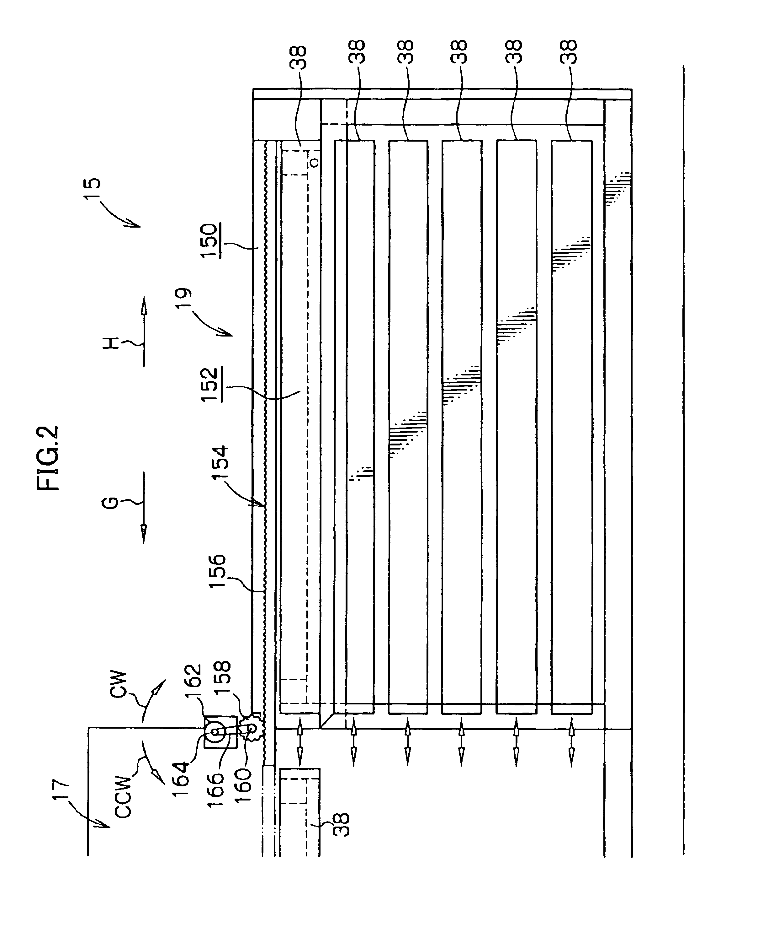
In a removing / conveying portion of a printing plate removing / supplying device, when one cassette among a plurality of cassettes is empty, the empty cassette is placed on a raising / lowering stand and moved to a loading space. Due to a spur gear being rotated clockwise by a motor, a sliding cover, with which the spur gear is engaging, is moved toward a removing portion such that an opening of a cassette stocker portion is opened. In this way, it is possible to refill and load printing plates from a top side of the cassette stocker portion into the empty cassette positioned at the loading space.

Description

CROSS-REFERENCE TO RELATED APPLICATION[0001]This application claims priority under 35 USC 119 from Japanese Patent Application No. 2003-83392, the disclosure of which is incorporated by reference herein.BACKGROUND OF THE INVENTION[0002]1. Field of the Invention[0003]The present invention relates to a printing plate removing / supplying device which removes a predetermined printing plate from plural cassettes in which printing plates are respectively accommodated, and conveys and supplies the predetermined printing plate to a section-to-be-supplied-to, which is a subsequent process.[0004]2. Description of the Related Art[0005]A technique in which, by using a printing plate (e.g., a PS plate, a thermal plate, a photopolymer plate) in which a recording layer (photosensitive layer) is provided on a support, an image is recorded directly by a laser beam or the like onto the photosensitive layer of the printing plate, has come to be developed as a printing plate exposing device. With this t...

Claims


Application Information

Patent Timeline
Patent Type & Authority Patents(United States)
IPC IPC(8): B65H31/24B65H3/08B65H1/26B65H1/30G03F7/20
CPCB41F27/1206B65H1/26B65H3/0825B65H3/44B65H2701/1928B65H2405/332B65H2405/35B65H2405/361B65H1/266
Inventor KOIZUMI, TAKASHIKAWAMURA, YOSHINORI
Owner FUJIFILM HLDG CORP
Why Eureka
Try Eureka