Compression release brake system
a brake system and compression release technology, applied in the direction of machines/engines, non-mechanical valves, output power, etc., can solve the problems of engine damage, engine cam not providing the optimal amount of valve displacement or lift, and the known loss-motion devices used for the above described purpose are complex and expensiv
- Summary
- Abstract
- Description
- Claims
- Application Information
AI Technical Summary
Problems solved by technology
Method used
Image
Examples
Embodiment Construction
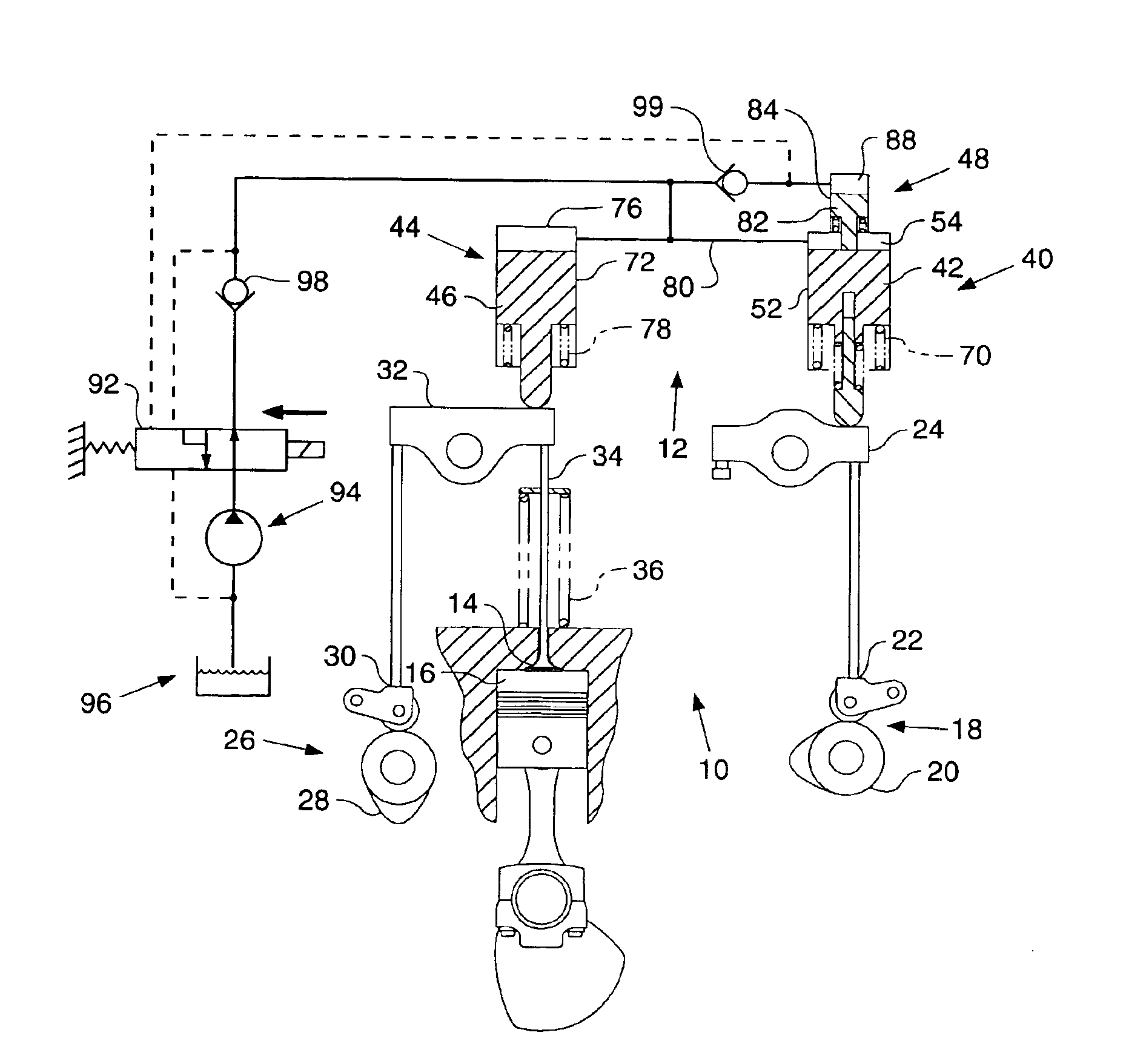
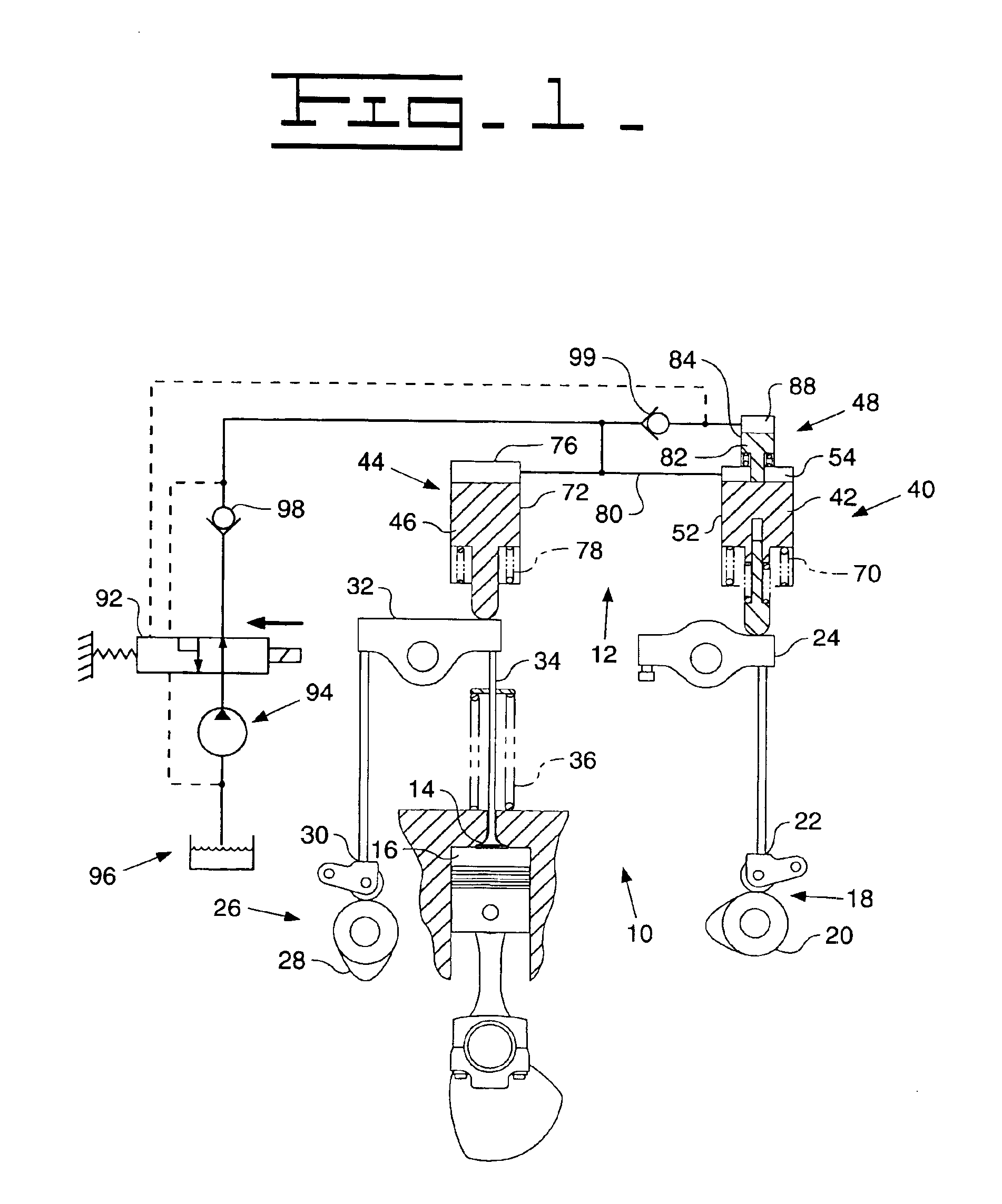
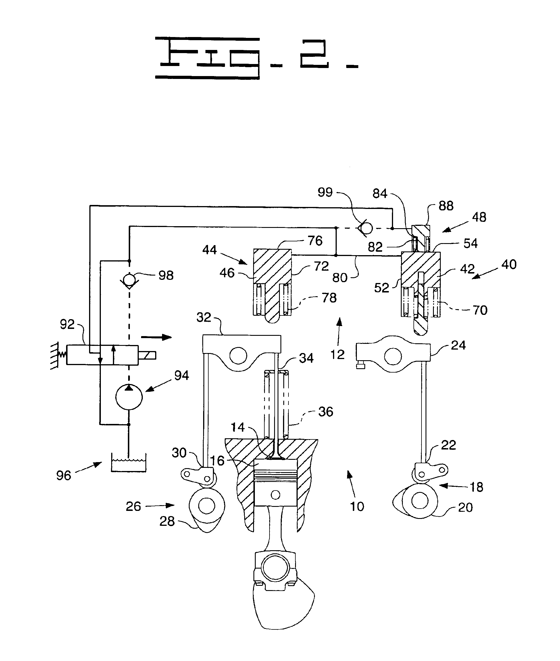
[0013]Referring first to FIGS. 1 and 2, a compression release brake system 10 includes a hydraulic apparatus 12 for controllably opening at least one exhaust valve 14 of at least one cylinder 16 of an engine (not shown) in response to motion of a cam actuator 18. The cam actuator 18 may be a rotating cam such as an injector cam 20 that is normally used to activate one or more fuel injectors, and may include a cam follower 22 and rocker arm arm 24 arranged to translate the rotary motion of the cam 20 into a linear driving motion, as is well known in the engine art. The engine valve 14 may include a similar cam driver 26 having an associated cam 28, cam follower 30, and rocker arm 32. The rocker arm 32 normally reciprocates according to the profile of the cam 28, in turn periodically opening the engine valve 14 by transferring motion to a push rod 34. A valve closing spring 36 acts to close the engine valve 14 when it is not held open by the rocker arm 32.
[0014]A master piston assembl...
PUM
 Abstract
Description
Claims
Application Information
 - R&D
- Intellectual Property
- Life Sciences
- Materials
- Tech Scout
- Unparalleled Data Quality
- Higher Quality Content
- 60% Fewer Hallucinations
Browse by: Latest US Patents, China's latest patents, Technical Efficacy Thesaurus, Application Domain, Technology Topic, Popular Technical Reports.
© 2025 PatSnap. All rights reserved.Legal|Privacy policy|Modern Slavery Act Transparency Statement|Sitemap|About US| Contact US: help@patsnap.com


