Deployment mechanism for stowable fins

a deployment mechanism and fin technology, applied in the field of deployment mechanisms for stowable fins, can solve the problems of reducing the likelihood of damage to the fin, complex and expensive design, construction and maintenance, and various relatively complex deployment mechanisms that have been developed, and achieves cost, weight and space saving advantages. the effect of simple and reliabl

Inactive Publication Date: 2005-06-14
RAYTHEON CO
View PDF15 Cites 45 Cited by
  • Summary
  • Abstract
  • Description
  • Claims
  • Application Information

AI Technical Summary

Benefits of technology

[0010]There is a need for a simple and reliable device to retain or lock stowable ordnance fins in a stowed configuration, support, deploy, lock stowable ordnance fins into a deployed configuration and, in some cases, control the fins in the deployed configuration. The present invention provides a deployment mechanism for stowing and deploying stowable fins that meets this need and provides further advantages in cost, weight and space savings.

Problems solved by technology

It also reduces the likelihood of damage to the fins during storage and handling.
Various relatively complex deployment mechanisms have been developed to permit the fins to be stowed, deployed and locked into place.
The mechanisms presently used to retain, deploy and control (if applicable) the fins tend to be relatively heavy, complex and expensive to design, build and maintain.
Moreover, some mechanisms occupy a relatively large volume within the missile, a significant disadvantage because of the limited space within the missile.

Method used


Image

  • Deployment mechanism for stowable fins
  • Deployment mechanism for stowable fins
  • Deployment mechanism for stowable fins

Examples


Embodiment Construction

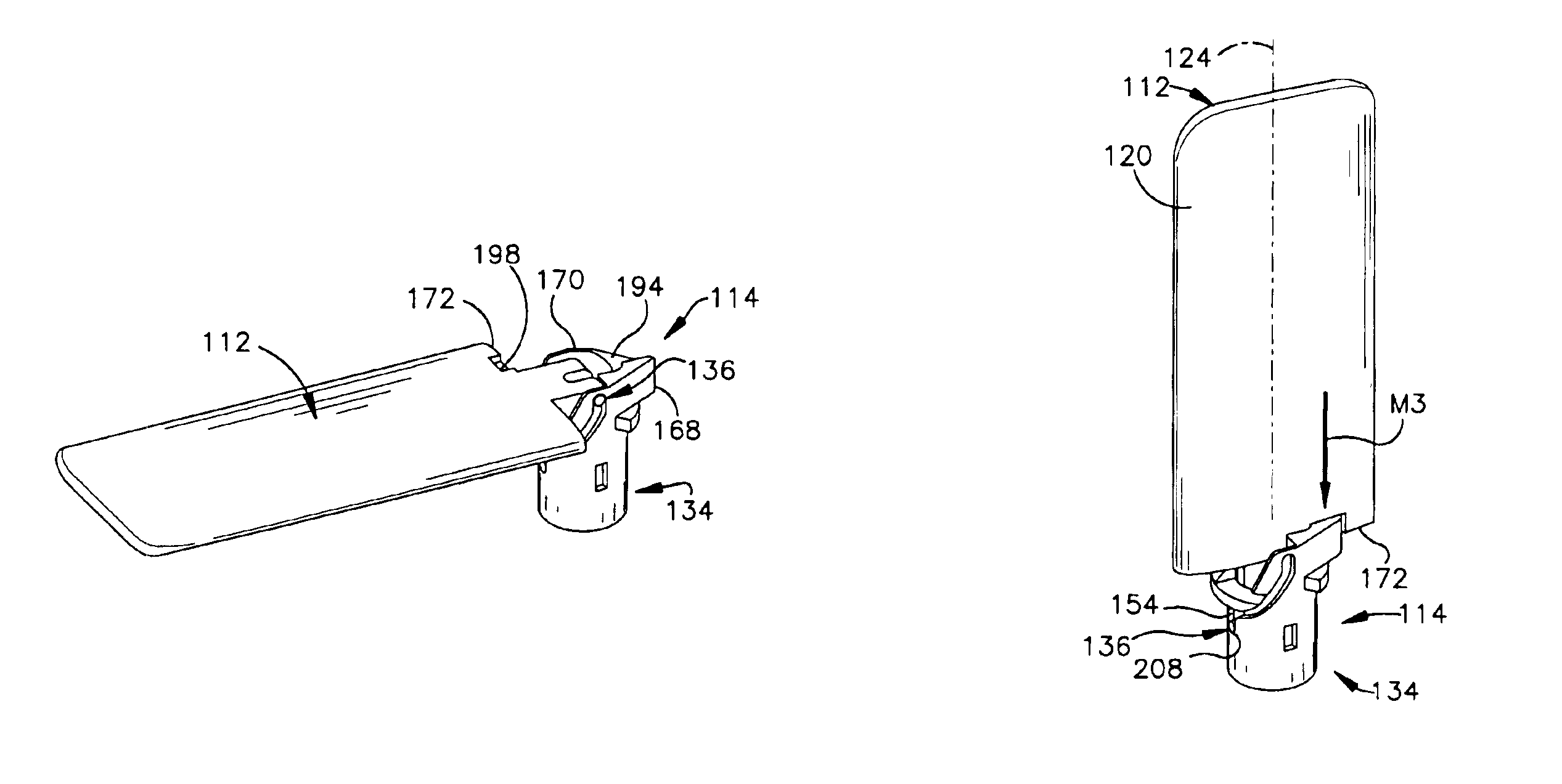
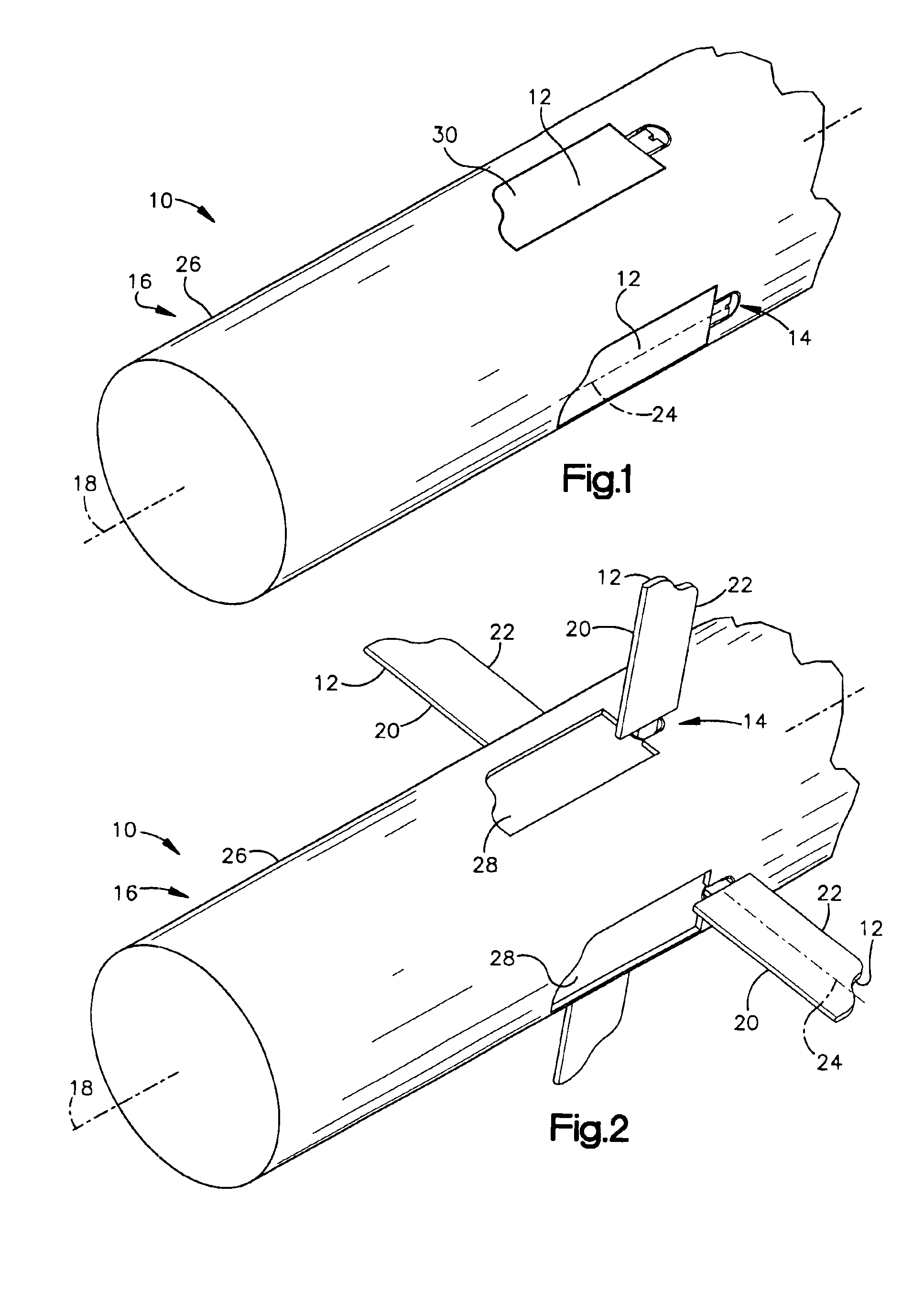
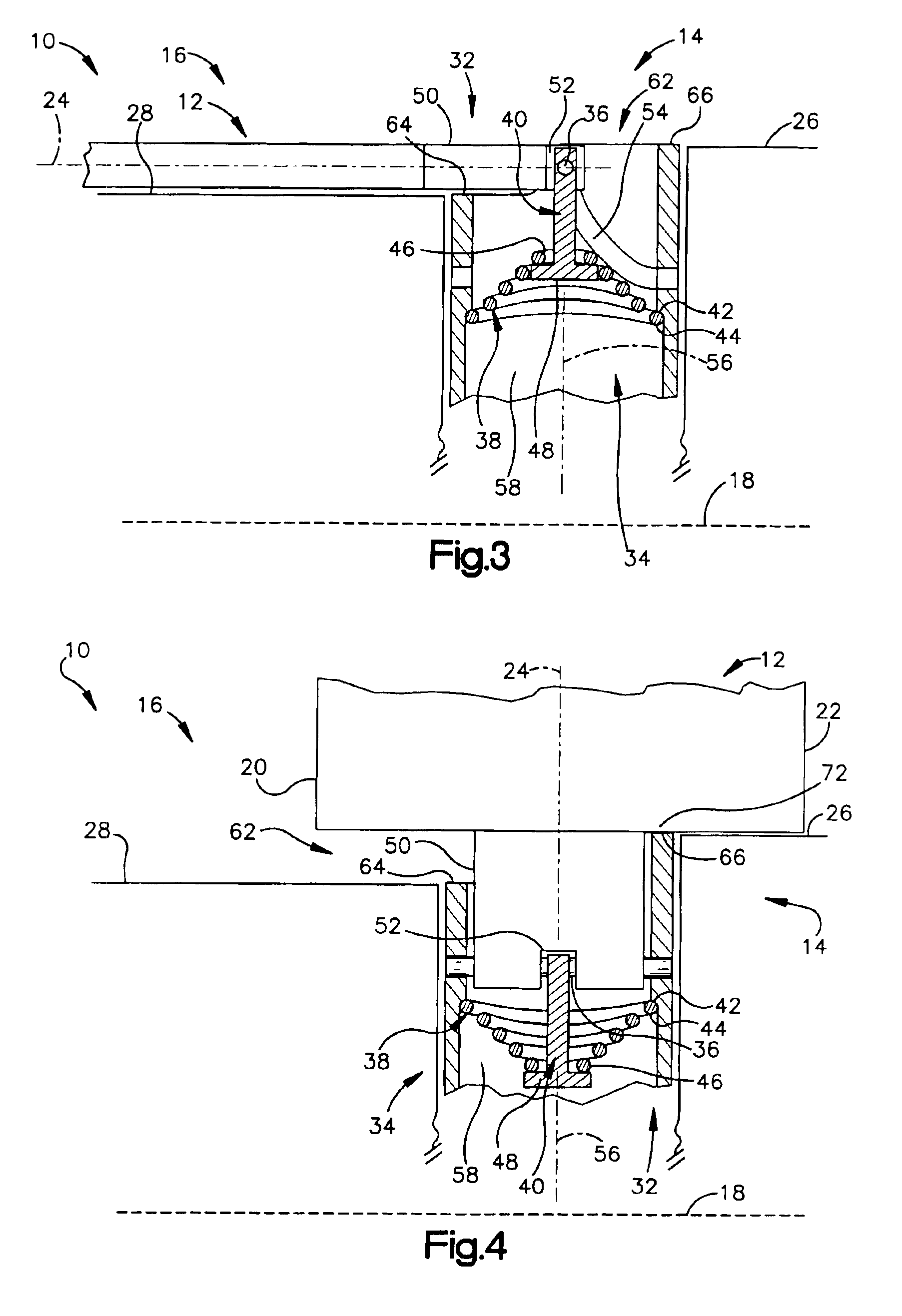
[0040]Referring now to the drawings, and initially to FIGS. 1 and 2, the present invention provides ordnance, such as a missile 10, having a plurality of fins 12 for stabilizing or controlling the missile during flight. The missile 10 includes at least one stowable fin 12 and a deployment mechanism 14 for moving the fin 12 from a stowed configuration (FIG. 1) to a deployed configuration (FIG. 2) so that the missile 10 can be stored or launched in a more compact configuration. The illustrated missile 10 has four fins 12 mounted to a generally cylindrical body (missile body) 16 having a longitudinal axis 18. Although the present description refers to the missile 10 shown in the drawings, the illustrated missile 10 represents any type of ordnance that uses stowable fins and is not limited to a missile.

[0041]Each fin 12 has a leading edge 20 and a trailing edge 22 that bound the width of the fin 12, and a longitudinal axis 24 that extends approximately along the length of the fin 12. Th...


PUM


Abstract

A deployment mechanism (414) in combination with a missile (10), guided projectile (410) or other ordnance that automatically pivots and rotates a fin (412) from a stowed orientation to a deployed orientation. The deployment mechanism (414) includes a tubular cam (434) having a retention mechanism (455) that retains the fin (412) simply and reliably in the stowed orientation. The tubular cam also guides the fin (412) quickly to the deployed orientation.

Description

[0001]This application is a continuation-in-part of U.S. patent application Ser. No. 10 / 102,032, now U.S. Pat. No. 6,761,331, by Rudolph A. Eisentraught, Martin A. Kebschull and John C. Parine, entitled MISSILE HAVING DEPLOYMENT MECHANISM FOR STOWABLE FINS, filed on Mar. 19, 2002.RIGHTS OF THE GOVERNMENT[0002]The invention described herein was developed with Government support under Contract No. DAAH01-00-C-0107 awarded by the U.S. Department of the Army. The Government has certain rights in this invention.FIELD OF THE INVENTION[0003]The present invention generally relates to ordnance having stowable fins, and, more particularly, to a deployment mechanism for stowing and deploying the fins.BACKGROUND OF THE INVENTION[0004]Many types of ordnance utilize two or more protruding surfaces to affect the fluid flow around the ordnance, thereby facilitating control of its trajectory toward a target. Exemplary types of such ordnance include missiles, rockets, guided projectiles, bombs, torpe...

Claims


Application Information

Patent Timeline
Patent Type & Authority Patents(United States)
IPC IPC(8): F42B10/00F42B10/14F42B10/60
CPCF42B10/14
Inventor DRYER, RICHARDEISENTRAUT, RUDOLPH ADOLPHKEBSCHULL, MARTIN ALLENPARINE, JOHN CHRISTOPHER
Owner RAYTHEON CO
Why Eureka
Try Eureka