
Banding reduction in incremental printing

a technology of incremental printing and banding, applied in the field of printing, can solve the problems of reducing the noticeability of the human eye, and achieve the effects of reducing the banding effect, reducing the cost of implementation, and reducing the speed

Inactive Publication Date: 2005-06-14
HEWLETT PACKARD DEV CO LP
View PDF4 Cites 2 Cited by
  • Summary
  • Abstract
  • Description
  • Claims
  • Application Information

AI Technical Summary

Benefits of technology

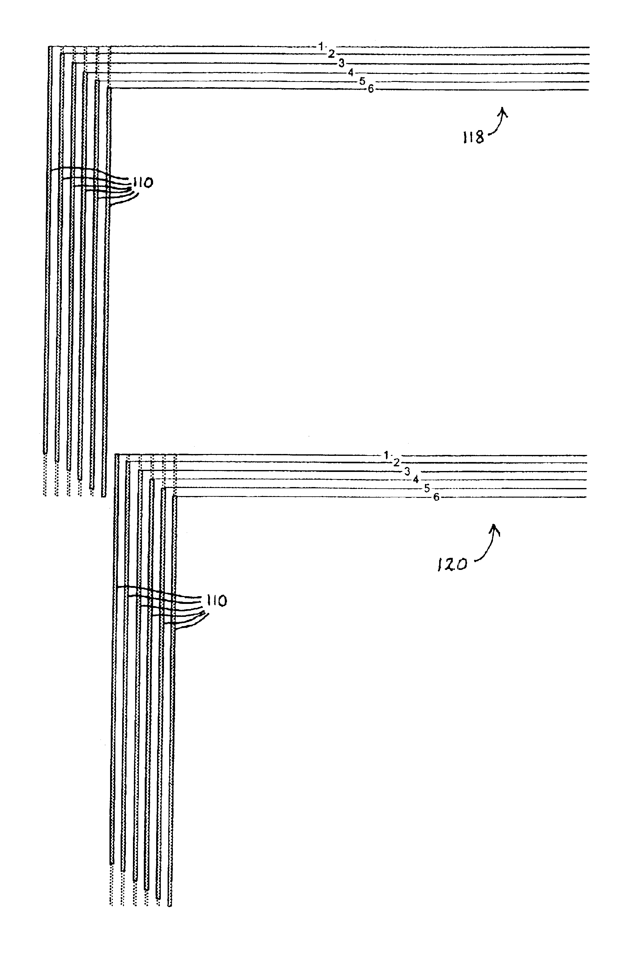
[0023]The method of the invention increases the print quality in two major ways. First, the banding errors from the different swaths do not reinforce one another since they lie on different points along the page, and second, the frequency of these (less noticeable) banding errors tends to be increased thereby reducing their noticeability to the human eye.
[0028]A significant advantage of this method of implementing the invention is that the invention can be implemented without any changes to the hardware (printer carriage, print cartridges, printheads, nozzle arrangements, etc.) used in the prior art, and thus it is inexpensive to implement, requiring only changes to the PC or print server software or to the printer firmware controlling the operation of the printer so that different sets of active nozzles (each of which can be thought of as providing a different “virtual pen”) can be brought into play for each physical pen.
[0029]A further advantage of this is that the invention can be implemented for those print jobs for which higher quality is specified, and for lower quality print jobs the same hardware can be used in conventional manner to provide e.g. single pass printing with overlapping swath boundaries.
[0030]A compromise can also be reached between speed and quality by defining a print mode in which the active and inactive sets are defined for each pen (with at least two of the pens having different inactive sets of corresponding ink ejection elements), but printing in a single pass mode. As will be described below, this allows a significant reduction in banding effects to be observed with only a minor reduction in speed relative to the maximum speed at the print resolution chosen.

Problems solved by technology

First, the banding errors from the different swaths do not reinforce one another since they lie on different points along the page, and second, the frequency of these (less noticeable) banding errors tends to be increased thereby reducing their noticeability to the human eye.

Method used


Image

  • Banding reduction in incremental printing
  • Banding reduction in incremental printing
  • Banding reduction in incremental printing

Examples


Embodiment Construction

[0051]There will now be described examples of the best mode contemplated by the inventors for carrying out the invention.

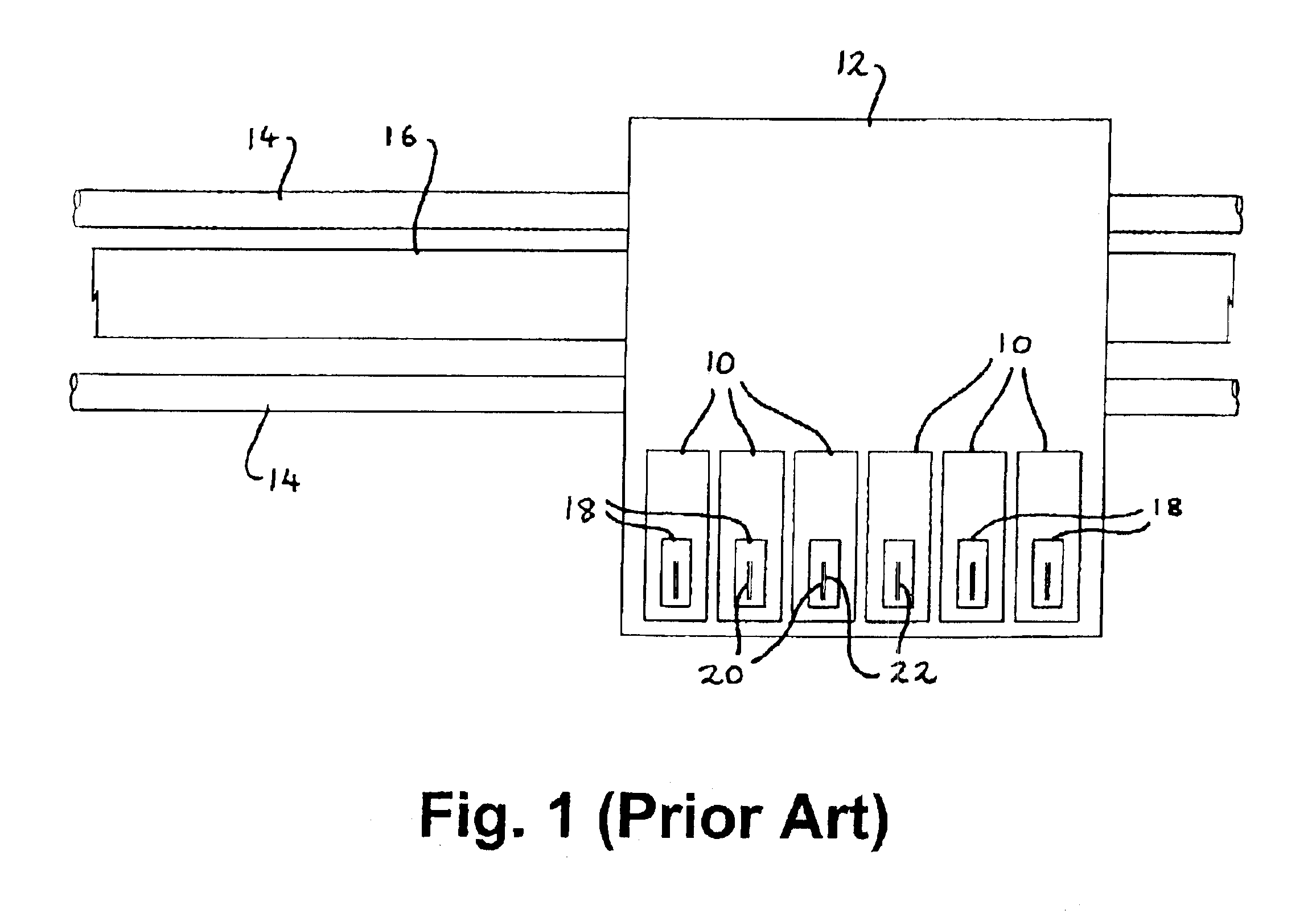
[0052]In FIG. 1 a conventional printhead is shown when printing with a preferred method of the invention with the only modification necessary being in the printer software or firmware.

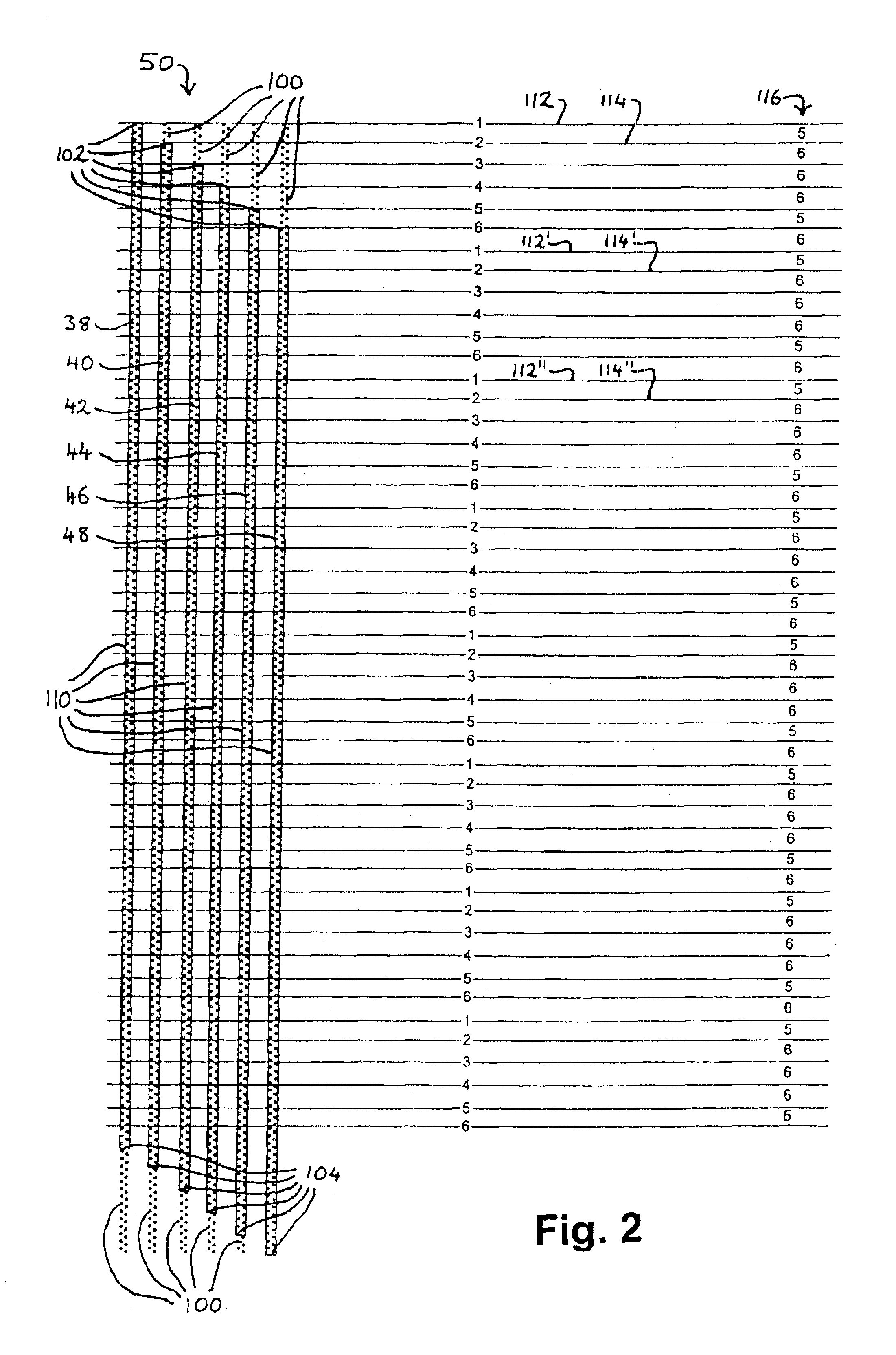
[0053]The nozzle configuration of FIG. 2 is a known array of six pens 38-48 each comprising two staggered rows of nozzles to give 300 nozzles per pen spaced at {fraction (1 / 600)} inch intervals along the media axis. (The pens from left to right are a dark magenta pen 38, a dark cyan pen 40, a yellow pen 42, a light magenta pen 44, a light cyan pen 46 and a black pen 48.)

[0054]However, the nozzles are controlled by the printing software (which may be resident in a PC sending a print job to the printer, in a print server, or in the printer itself, for example) such that each pen has a set of inactive nozzles 100 at one or both ends of the pen and a set of active nozzles 110. In FIG. 2 ...


PUM


Abstract

A method of printing with a printer of the type comprising a substantially linear arrangement of parallel pens mounted on a scan axis, each pen comprising an array of ink ejection elements, comprises printing a plurality of swaths, each from a different pen, on a printing medium between successive incremental advances of said medium in a printing advance direction (PAD) relative to the pens wherein said swaths are printed such that the boundaries of at least two of the swaths are offset from one another in the PAD. In a preferred method of the invention, the nozzles of the various pens are divided into active and inactive sets of nozzles, such that only the active nozzles are used to print the swaths and so that the different active nozzle sets each have offset endpoints in the PAD to print offset swath boundaries.

Description

CROSS-REFERENCE TO RELATED PATENT APPLICATIONS[0001]GB Priority Application 0209942.2, filed Apr. 30, 2002 including the specification, drawings, claims and abstract, is incorporated herein by reference in its entirety.FIELD OF THE INVENTION[0002]This invention relates to printing using printers which incrementally advance the printing medium relative to the printhead and more particularly printing methods and printer control software or circuitry for reducing the amount of banding arising from swath printing between advances.BACKGROUND OF THE INVENTION[0003]Printers such as inkjet printers generally employ printheads which are mounted on a scan axis for printing in a swath across a sheet of a print medium. The print medium, whether or not of paper, may be referred to herein as a “page” for simplicity, although any print-receiving medium is encompassed by this term whether in page format, in the form of an endless web, or in the form of an article such as an envelope which is fed th...

Claims


Application Information

Patent Timeline
Patent Type & Authority Patents(United States)
IPC IPC(8): B41J11/42B41J2/21
CPCB41J11/42B41J2/2132
Inventor KROUSS, PAUL R.
Owner HEWLETT PACKARD DEV CO LP
Learn More