Network cooled coated wall

a technology of network cooling and coating walls, applied in the direction of liquid fuel engines, machines/engines, efficient propulsion technologies, etc., can solve the problems of limited performance of superalloy metallic substrates, high cost of superalloys, and inability to meet the requirements of so as to improve the cooling of thermal barrier coatings. the effect of the coating itsel

Inactive Publication Date: 2005-06-14
GENERAL ELECTRIC CO
View PDF10 Cites 107 Cited by
  • Summary
  • Abstract
  • Description
  • Claims
  • Application Information

AI Technical Summary

Problems solved by technology

However, the combustion gases must be contained in the engine by various components which are therefore subject to heating therefrom.
These superalloys are expensive, but maximize the high temperature strength of the hot components for achieving the desired long useful life thereof for reducing maintenance operations and corresponding costs.
However, the performance of superalloy metallic substrates, and the various forms of conventional thermal barrier coatings and their corresponding bond coats is nevertheless limited by the ability of the air coolant to cool these materials for maintaining them below their maximum operating temperatures.

Method used


Image

  • Network cooled coated wall
  • Network cooled coated wall
  • Network cooled coated wall

Examples


Embodiment Construction

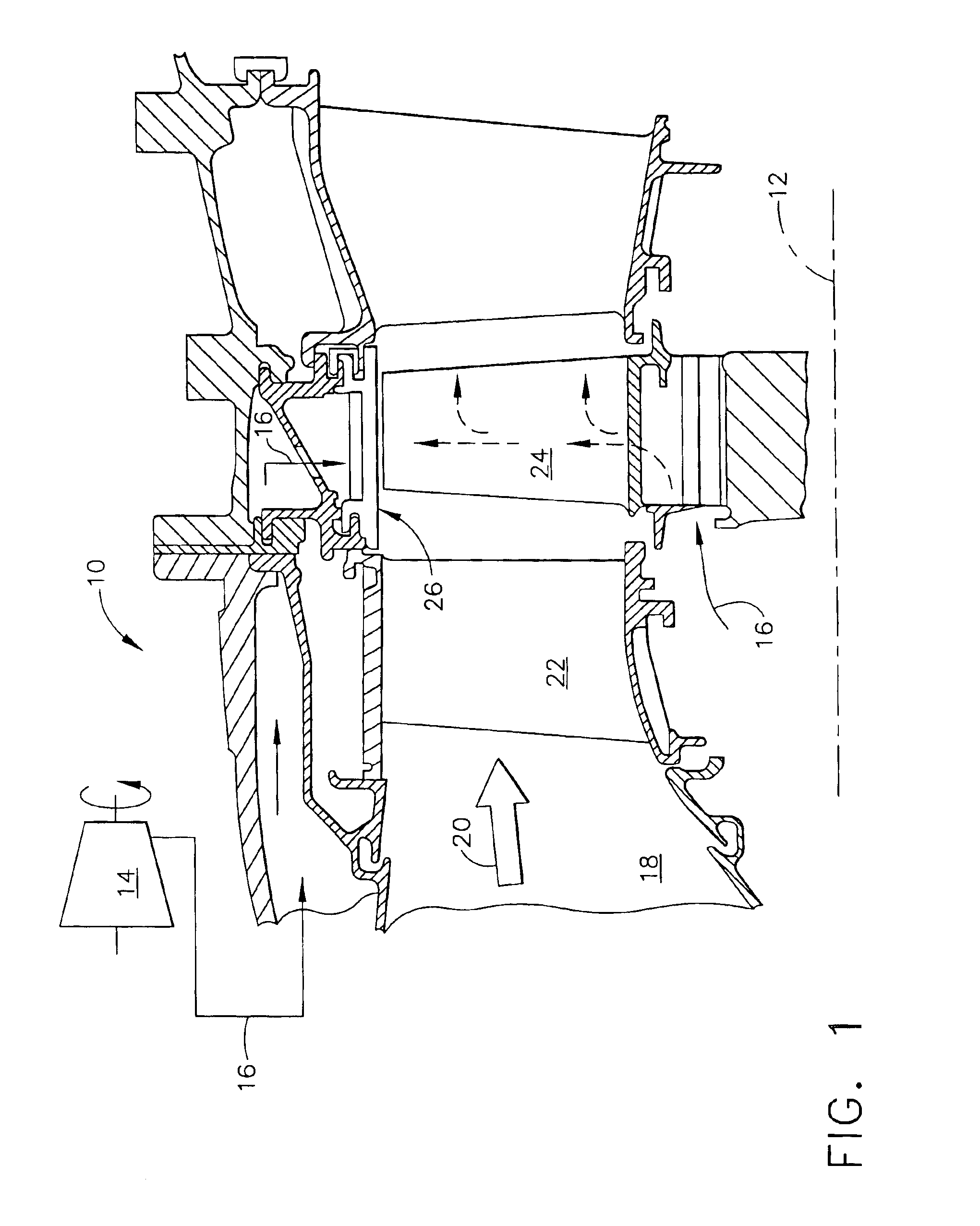
[0021]Illustrated in FIG. 1 is a portion of a gas turbine engine 10 which is axisymmetrical about a longitudinal or axial centerline axis 12. The engine includes a multistage axial compressor 14 that pressurizes air 16 which is suitably channeled to an annular combustor 18, shown in aft part.

[0022]The air is mixed with fuel in the combustor and ignited for generating hot combustion gases 20 which are discharged therefrom between the stator vanes 22 of a high pressure turbine nozzle. The vanes guide the combustion gases through of row of high pressure turbine rotor blades 24 which extend radially outwardly from a supporting rotor disk that is joined in turn to the compressor for providing power thereto during operation.

[0023]Another turbine nozzle follows the first stage rotor blades 24 for further guiding the combustion gases downstream to a low pressure turbine (not shown) which extracts further energy for powering an upstream fan in a typical turbofan gas turbine engine applicatio...


PUM


Abstract

A turbine wall includes a metal substrate having front and back surfaces. A thermal barrier coating is bonded atop the front surface. A network of flow channels is laminated between the substrate and the coating for carrying an air coolant therebetween for cooling the thermal barrier coating.

Description

BACKGROUND OF THE INVENTION[0001]The present invention relates generally to gas turbine engines, and, more specifically, to component cooling therein.[0002]In a gas turbine engine, air is pressurized in a compressor and mixed with fuel for generating hot combustion gases in a combustor. Energy is extracted from the combustion gases in a high pressure turbine for powering the compressor, and additional energy is extracted in a low pressure turbine which powers a fan in a turbofan aircraft engine application, or drives an output shaft for marine and industrial applications.[0003]Engine efficiency may be maximized by maximizing the temperature of the combustion gases from which energy is extracted. However, the combustion gases must be contained in the engine by various components which are therefore subject to heating therefrom.[0004]Typical components exposed to the hot combustion gases include the liners of the combustor, the vanes and bands of turbine nozzles, and rotor blades and ...

Claims


Application Information

Patent Timeline
Patent Type & Authority Patents(United States)
IPC IPC(8): F01D25/12F01D11/24F01D25/08F01D11/08F01D5/28F02C7/18F02C7/28
CPCF01D5/288F01D11/24F01D25/12Y02T50/675Y02T50/67F05D2260/204Y02T50/60
Inventor LEE, CHING-PANGDAROLIA, RAMGOPAL
Owner GENERAL ELECTRIC CO
Why Eureka
Try Eureka