
Gradient adjusting structure of a treadmill

Inactive Publication Date: 2005-06-14
P & F BROTHER INDAL
View PDF2 Cites 10 Cited by
  • Summary
  • Abstract
  • Description
  • Claims
  • Application Information

AI Technical Summary

Benefits of technology

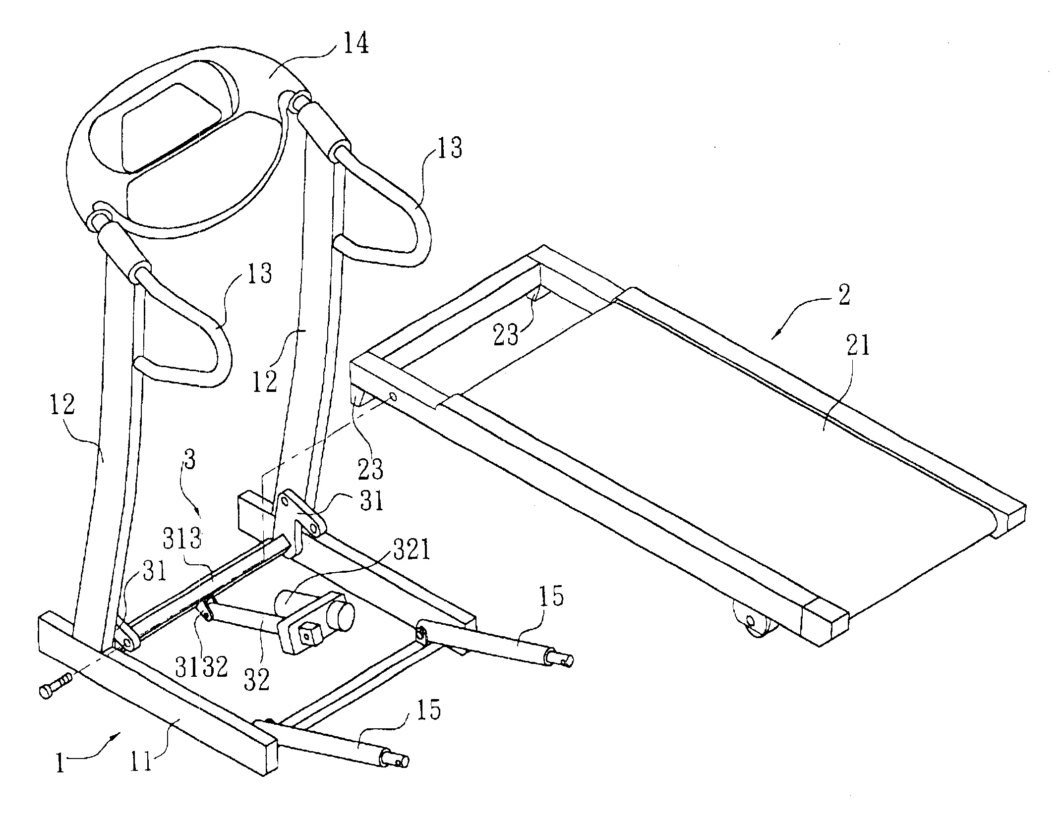
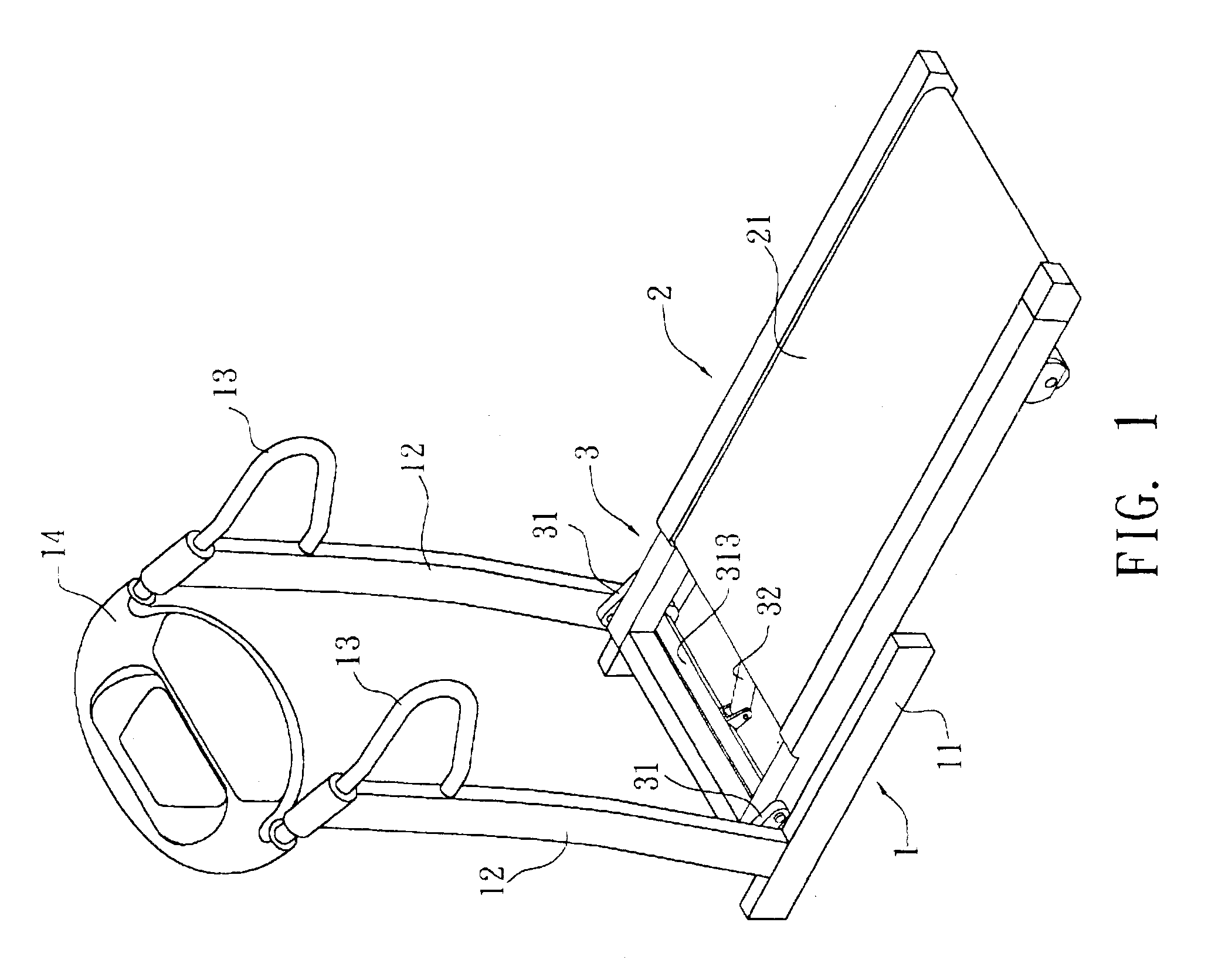
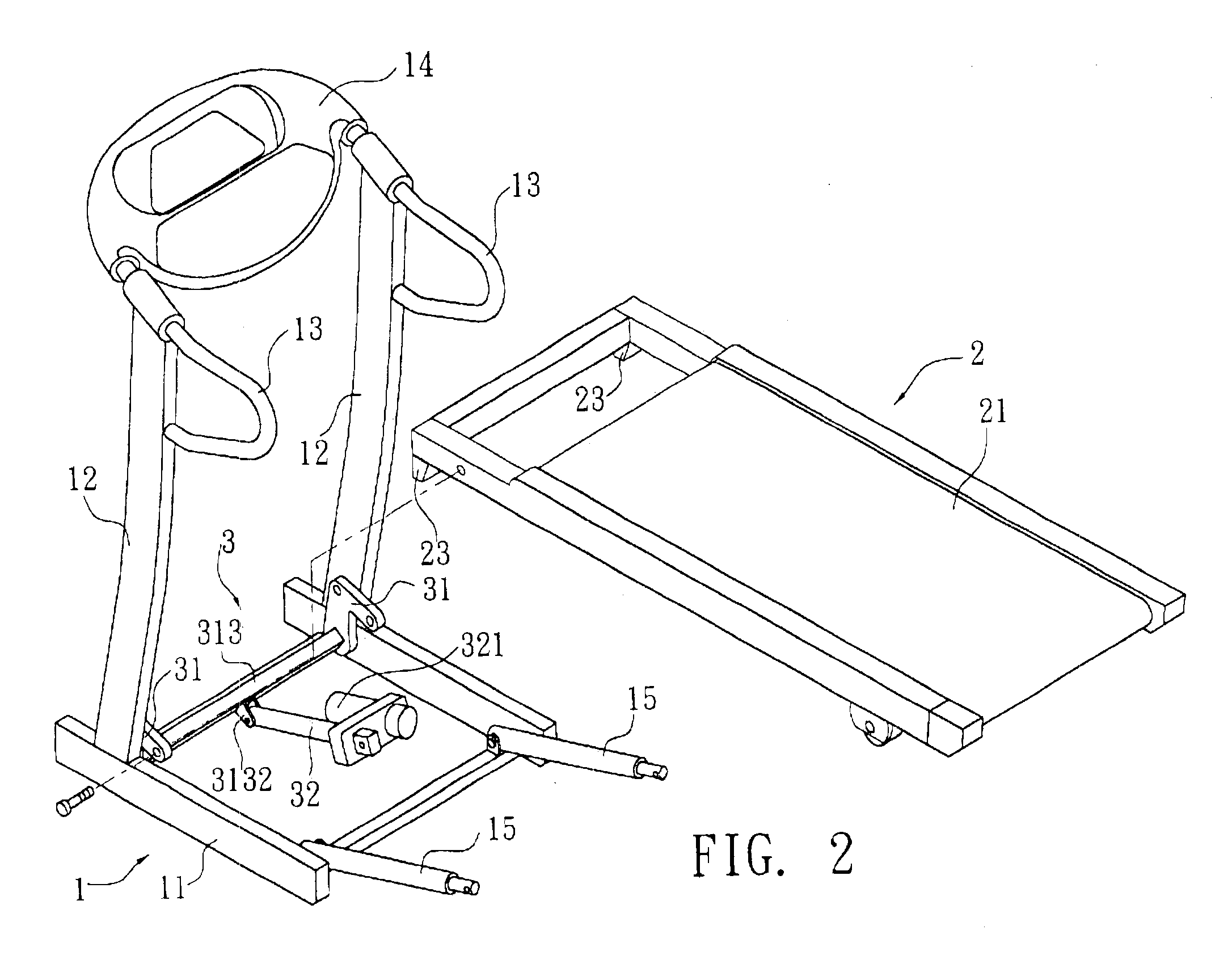
[0005]It is therefore a primary object of the present invention to provide a gradient adjusting structure of a treadmill including a base seat and a tread platform mounted between two columns of the base seat. The bottom of front end of the tread platform has at least one stop block. The gradient adjusting device has two symmetrical adjusting members and a telescopic rod. Each adjusting member has a first and a second ends containing a certain angle and outward extending. The center of the adjusting member is pivotally connected with inner face of the column near bottom end thereof. The first ends of the adjusting members are respectively pivotally connected with two sides of front end of the tread platform. A transverse beam is fixed between the second ends of the adjusting members and positioned under the bottom of front end of the tread platform, whereby the stop block of the tread platform can abut against the transverse beam. One end of the telescopic rod is pivotally connected with one side of the transverse beam, while the other end of the telescopic rod is pivotally connected with the bottom of the tread platform. When the tread platform is lowered to the bottom, the stop blocks of the bottom of front end of the tread platform will abut against the transverse beam of the adjusting members so as to support the tread platform. Accordingly, the weight loaded on the tread platform and the tread force are shared by the transverse beam with the tread platform. Also, the bending stress exerted onto the telescopic rod is minimized to prevent the telescopic rod from being worn.
[0006]It is a further object of the present invention to provide the above gradient adjusting structure of the treadmill in which when the rear end of the tread platform is upward folded about the pivot sections between the adjusting members and the columns of the base seat, the first ends of the adjusting members pivotally connected with the tread platform are upward swung along with the tread platform. Accordingly, the force arm between the pivot sections of the adjusting members pivotally connecting with the columns and the tread platform is shortened. Therefore, the folded tread platform can be stably supported.

Problems solved by technology

However, this is not so helpful to the drag worm 81 with respect to bending stress and even the sleeve 82 will interfere with the rotation of the drag worm 81.
Therefore, after folded, the tread frame 6 has poor support strength and can be hardly stably supported.

Method used


Image

  • Gradient adjusting structure of a treadmill
  • Gradient adjusting structure of a treadmill
  • Gradient adjusting structure of a treadmill

Examples


Embodiment Construction

[0018]Please refer to FIGS. 1 to 3. The present invention is related to a gradient adjusting structure of a treadmill including a base seat 1, a tread platform 2 and a gradient adjusting device 3.

[0019]The left and right sides of the base seat 1 respectively have two sidebars 11. An upward extending column 12 is disposed at front end of each side bar 11. A handle 13 is disposed at top end of the column 12. A controlling panel 14 is mounted between the two handles 13 for a user to hold when treading. The controlling panel 14 is for the user to control and adjust the treading speed and slope of the tread platform 2. One end of each of two support levers 15 is pivotally connected with rear end of the side bar 11. The other end of the support lever 15 is pivotally connected with one side of the middle section of the tread platform 2.

[0020]The front end of the tread platform 2 is mounted between the two columns 12 of the base seat 1. A tread belt 21 is disposed in the tread platform 2. T...


PUM


Abstract

A gradient adjusting structure of a treadmill includes two symmetrical adjusting members and a telescopic rod. The center of the adjusting member is pivotally connected with inner face of the column near bottom end thereof. The first ends of the adjusting members are respectively pivotally connected with two sides of front end of the tread platform. A transverse beam is fixed between the second ends of the adjusting members and positioned under the bottom of front end of the tread platform, whereby the stop block of the tread platform can abut against the transverse beam. One end of the telescopic rod is pivotally connected with one side of the transverse beam, while the other end of the telescopic rod is pivotally connected with the bottom of the tread platform.

Description

BACKGROUND OF THE INVENTION[0001]The present invention is related to a gradient adjusting structure of treadmill, which is able to stably support the treadmill.[0002]A conventional treadmill is generally equipped with a gradient adjusting structure for changing the slope of the tread platform and enhancing exercising effect. FIG. 9 shows an adjustment device for adjusting the height of the frame of the conventional treadmill. The adjustment device includes two linking plates 7 each of which is formed with a frame pivot hole 71, a front support lever pivot hole 72 and a long shaft pivot hole 73. The frame pivot hole 71 and the front support lever pivot hole 72 are respectively positioned at front end and the middle of the linking plate 7 in higher positions. The long shaft pivot hole 73 is positioned at rear end of the linking plate 7 in a lower position. Via the frame pivot holes 71, the linking plates 7 are respectively pivotally disposed on two sides of front end of the tread fram...

Claims


Application Information

Patent Timeline
IPC IPC(8): A63B22/00A63B22/02
CPCA63B22/0023A63B2210/56
Inventor LO, PAI HUA
Owner P & F BROTHER INDAL
Learn More