Apparatus for mounting a frac blender on a transport vehicle

a technology for transport vehicles and blenders, applied in transportation items, elevators, borehole/well accessories, etc., can solve the problems of dangerous rollover potential, heavy bending on the hinge system as well as the drive system, and difficult to maintain balance, so as to reduce the bending stress and reduce the binding stress

Inactive Publication Date: 2005-01-06
LIBERTY OILFIELD SERVICES LLC
View PDF3 Cites 6 Cited by
  • Summary
  • Abstract
  • Description
  • Claims
  • Application Information

AI Technical Summary

Benefits of technology

[0012] Typically, the support frame has both a horizontal span and a vertical span and the platform substantially spans the horizontal span. A pair of slide rails are positioned to span the vertical span of the support frame in spaced parallel relationship at opposite sides of the horizontal span. A pair of slides are mounted, one each on each slide rail, and the platform spans the pair of slides and is secured to each of said slides. A transfer bar spans the space between the spaced slide rails and engages the slides wherein the drive system is connected directly to the transfer bar, the transfer bar being slip mounted to the slide rails for permitting relative movement between the slide rails and the transfer bar. The drive system is also slip mounted for relative movement between the drive system and the support frame for minimizing any binding forces between the drive system and the transfer bar.
[0013] In the preferred embodiment, the support frame has an upper, elongated mounting bracket and the slide rails are mounted on and depend from the upper bracket. One or more jack screw blocks are mounted on the transfer bar. The drive system comprises a vertical screw having one end mounted on the upper bracket and extending axially through the jack screw block. As the jack screw is driven to rotate about the screw, the transfer block moves axially along the screw, moving the slides along the rail. The frac blender is mounted on slides and moves therewith. The transfer bar is slip coupled to the slides to minimize any bending stress on the screw drive system. In the preferred embodiment the lower ends of the screw and the slide rails are also secured in fixed relationship with the support frame and chassis of the transport vehicle.
[0014] The system of the subject invention provides a method for supporting a frac blender on a transport vehicle in a manner permitting the frac blender to be moved between an upper stowed position and a lower operating position along a linear, vertical path by securing a support frame having a vertical reach to a transport vehicle, the support member having a vertically extending slide rail, and mounting a lift member on the slide rail for movement along the vertical reach of the support frame. The frac blender is mounted on the lift member and drive means are provided for driving the lift member between the upper and lower positions along the slide. It is an important feature of the method that the connection between the drive system and the lift member is a slip connection to reduce binding stresses.

Problems solved by technology

This is an awkward mounting system at best and places tremendous stress on the hinge system as well as the drive system for moving the blender between positions.
In addition, such massive units are difficult to keep in balance during movement between positions even under the best of circumstances, creating a hazardous rollover potential.
In the field, where uneven terrain is often present as well as numerous environmental conditions, it is difficult to maintain balance and the resulting binding stresses can generate wear and tear and frequent breakdowns.

Method used


Image

  • Apparatus for mounting a frac blender on a transport vehicle
  • Apparatus for mounting a frac blender on a transport vehicle
  • Apparatus for mounting a frac blender on a transport vehicle

Examples


Embodiment Construction

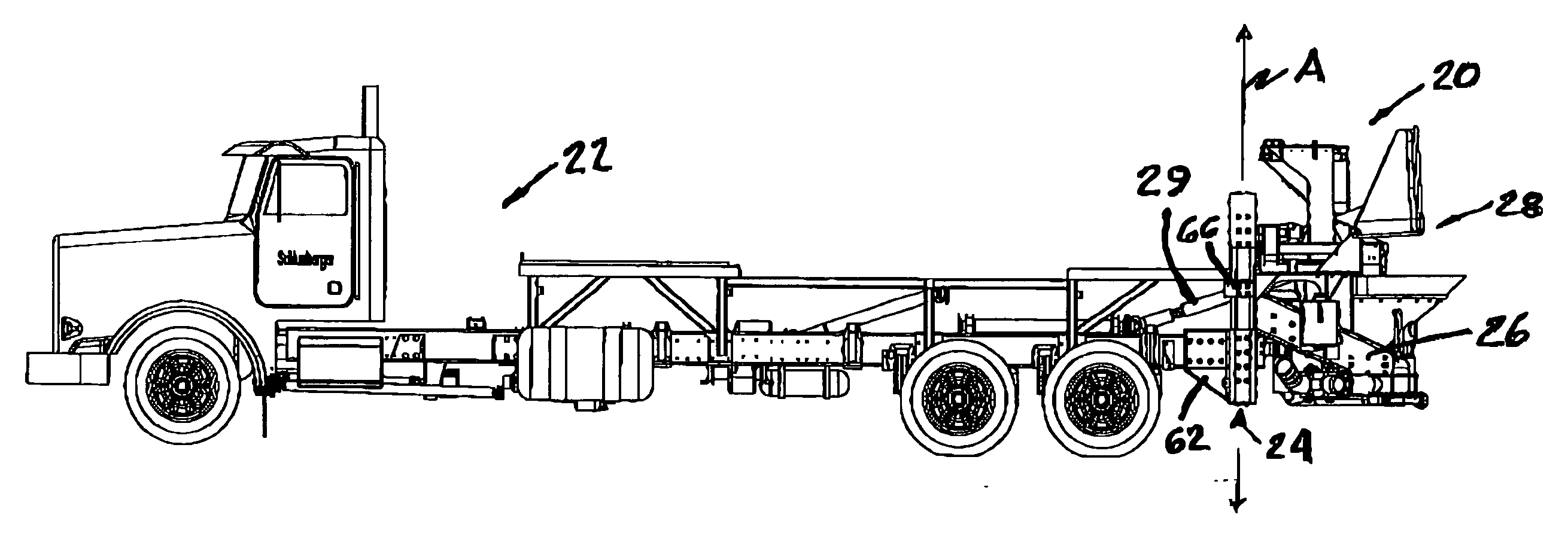
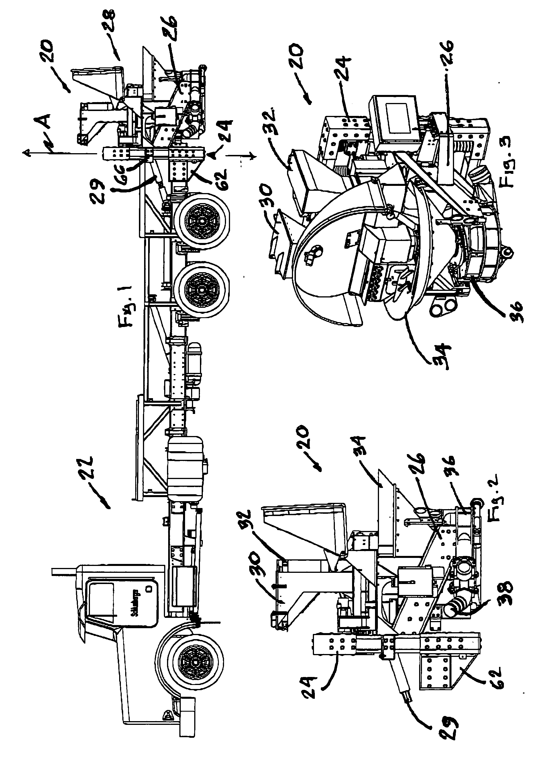
[0030] The fracture blender or mixer system 20 (or more commonly the frac blender) of the preferred embodiment is shown as mounted on a transport truck 22 in FIG. 1. The main components of the system are a lift frame 24, a support cage or base 26 and the frac blender 28. The drive train 29 is powered via hydraulic motors mounted on the truck chassis. The entire frac blender system of the subject invention is supported on the cage 26, which is in turn, mounted on the lift frame 24. The lift frame 24 is mounted on the truck chassis. The frac blender and cage are moveable along a vertical, straight linear path as indicated by line A for moving the blender between the raised transport position as shown in FIG. 1 and a lowered operating position.

[0031]FIGS. 2 and 3 illustrate the frac blender system 20 in greater detail. The blender 28 is of relatively typical design and includes a pair of receptacles 30, 32, for introducing dry materials to the mix. The additive and proppant are introd...


PUM

PropertyMeasurementUnit
relative movementaaaaaaaaaa
binding forcesaaaaaaaaaa
permeabilityaaaaaaaaaa

Abstract

A support system for supporting a frac blender or other heavy load on a transport vehicle includes a support frame having vertically extending slides for a lift platform whereby the load may be moved between a stowed position and an operating position along a vertical, linear path within the limits of the support frame. The drive system and the lift platform are slip connected to the frame for minimizing bending stress as the load is moved between positions

Description

BACKGROUND OF THE INVENTION [0001] 1. Field of the Invention [0002] The subject invention is related to a method and apparatus for mounting a heavy load on a transport vehicle in such a manner that the load may be moved between a stowed position and an operating position along a vertical path and is particularly directed to a method and apparatus for mounting a frac blender. [0003] 2. Discussion of the Prior Art [0004] Fracturing was first employed to improve production from marginal wells in the late 1940's. Following an explosion of the practice in the mid-1950's and a considerable surge in the mid-1980's, massive hydraulic fracturing grew to become a dominant production / stimulation technique, primarily for low permeability reservoirs in North America. By the mid-1990's, forty percent of new oil wells and seventy percent of gas wells in the United States were fracture treated. With improved fracturing capabilities, and the advent of high permeability fracturing, the practice has e...

Claims


Application Information

Patent Timeline
Patent Type & Authority Applications(United States)
IPC IPC(8): B60P1/00B66B1/00B66F3/08
CPCB66F3/08B60P1/00
Inventor PHAM, HAUGUERRERO, GUILLERMOLEUGEMORS, EDWARDPESSIN, JEAN-LOUIS
Owner LIBERTY OILFIELD SERVICES LLC
Why Eureka
Try Eureka