Flow diagnostic system

a flow diagnostic and flow control technology, applied in adaptive control, instruments, nuclear elements, etc., can solve the problems of impulse line clogging, pressure drop and increased turbulence, adversely affecting calibration,

Inactive Publication Date: 2005-06-14
ROSEMOUNT INC
View PDF305 Cites 119 Cited by
  • Summary
  • Abstract
  • Description
  • Claims
  • Application Information

AI Technical Summary

Benefits of technology

[0011]The diagnostic application can be provided over a network from an application service provider (ASP) or other source and can run on the control system, the ASP or another remote computer.

Problems solved by technology

Flow around the discontinuity causes both a pressure drop and increased turbulence.
Impulse lines can become plugged over time, which also adversely affects calibration.
This check pulse causes a control system connected to the transmitter to disturb the flow.
These known methods rely on providing static pressure sensors or disassembly of the flow meter, increasing complexity and reducing reliability.
These known methods do not provide for diagnosing the condition of the primary element.

Method used


Image

  • Flow diagnostic system
  • Flow diagnostic system
  • Flow diagnostic system

Examples


first embodiment

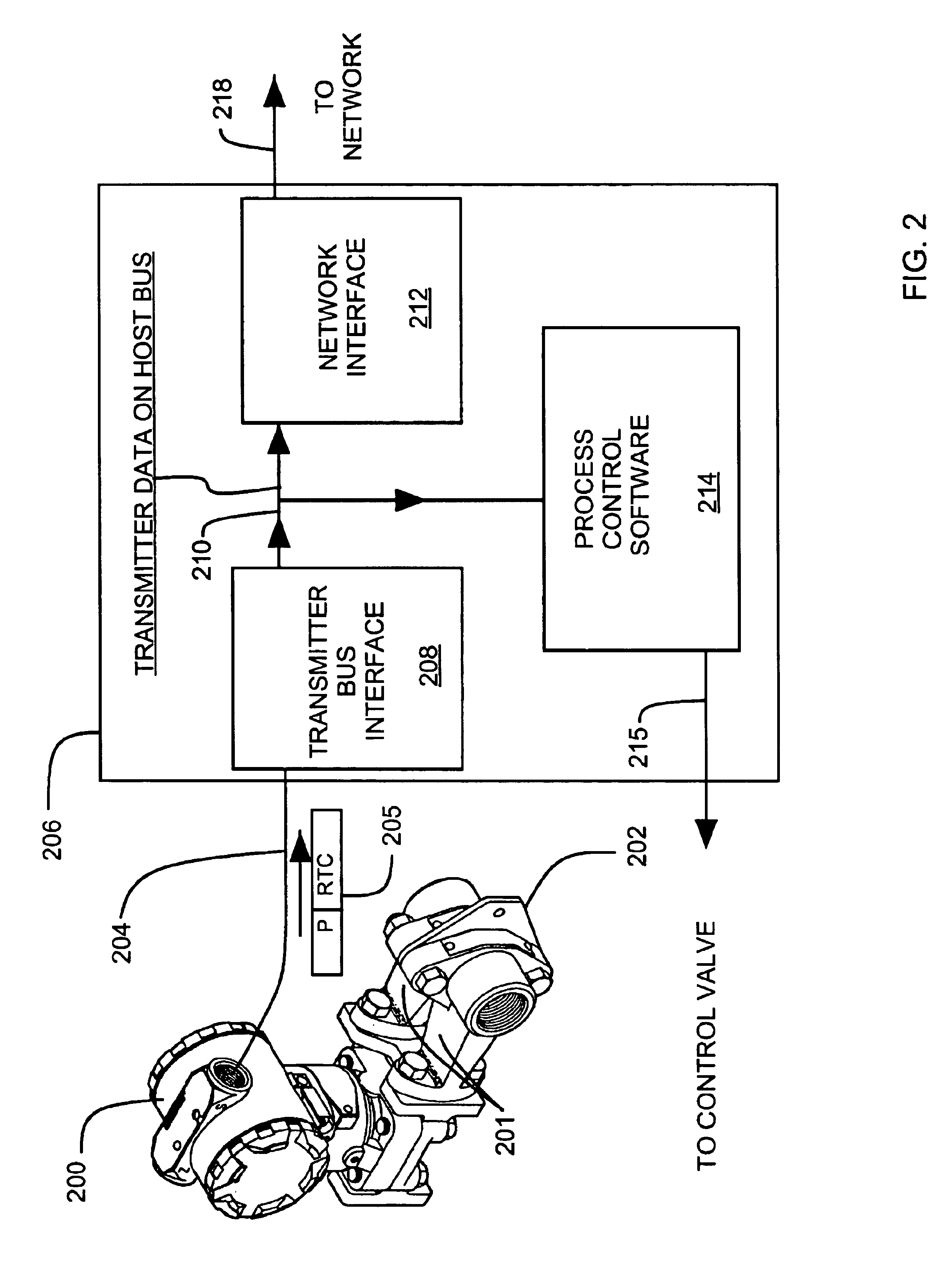
[0039]FIG. 2 is a schematic illustration of a control system 206 that is part of a flow diagnostic system such as flow diagnostic system 100 in FIG. 1.

[0040]Pressure transmitter 200 is coupled via impulse lines 201 to an integral orifice plate 202 in a fluid flow system. Pressure transmitter 200 couples to control system 206 along line 204. The pressure transmitter generates digital pressure data (P) and associated digital real time clock readings (RTC) as illustrated at 205. The real time clock readings provided by the transmitter 200 with each pressure reading indicate the relative time that each pressure reading is taken by the transmitter 200. In an instance where the transmitter generates pressure readings at a generally constant rate, the real time clock reading can be as simple as a sequential number for each reading. In an instance where the pressure reading are somewhat more irregularly spaced in time, the real time clock reading can be an approximate time that each reading...

second embodiment

[0043]FIG. 3 is a schematic illustration of a control system 306 that is part of a flow diagnostic system such as flow diagnostic system 100 in FIG. 1.

[0044]Pressure transmitter 300 is coupled via impulse lines 301 to an integral orifice plate 302 in a fluid flow system. Pressure transmitter 300 couples to control system 306 along line 304. The pressure transmitter generates digital pressure data (P) as illustrated at 305. Transmitter 300 may or may not generate real time clock readings, depending on the design of the transmitter.

[0045]In an instance where the transmitter 300 generates real time clock readings, these reading are coupled through transmitter bus interface 308 to real time clock circuit 318 via a bus 310 that is internal to control system 306. Real time clock circuit 318 then generates a corresponding synchronized real time clock reading that is synchronized with other real time clock readings in the control system 306. This synchronization allows for synchronized comp...


PUM

PropertyMeasurementUnit
frequencyaaaaaaaaaa
pressureaaaaaaaaaa
timeaaaaaaaaaa

Abstract

A flow diagnostic system for a flow sensing element and impulse lines. A pressure transmitter coupled to the impulse lines provides digital pressure data to a control system. The control system provides the pressure data and real time clock readings to a diagnostic application. The diagnostic application calculates a difference between current pressure data and its moving average. A condition of the primary element or impulse lines is diagnosed from a current pressure data set relative to an historical data set. The diagnostic application is downloadable from an application service provider (ASP). The application can run on the control system, a remote computer or the ASP. A diagnostic report is preferably provided.

Description

CROSS-REFERENCE TO RELATED APPLICATIONS[0001]This is a Continuation-In-Part of U.S. application Ser. No. 09 / 257,896, filed Feb. 25, 1999 now abandoned which is a Continuation-In-Part of U.S. application Ser. No. 08 / 623,569, filed Mar. 28, 1996, now U.S. Pat. No. 6,017,143, and this application is also a Continuation-In-Part of U.S. application Ser. No. 09 / 383,828, filed Aug. 27, 1999 now U.S. Pat. No. 6,654,697.FIELD OF THE INVENTION[0002]The present invention relates to fluid process control systems. In particular, the present invention relates to diagnostic systems for fluid flow in process control systems.BACKGROUND OF THE INVENTION[0003]Fluid flow meters are used in industrial process control environments to measure fluid flow and provide flow signals for flow indicators and controllers. Inferential flow meters measure fluid flow in a pipe by measuring a pressure drop near a discontinuity within the pipe. The discontinuity (primary element) can be an orifice, a nozzle, a venturi...

Claims


Application Information

Patent Timeline
Patent Type & Authority Patents(United States)
IPC IPC(8): G01F1/34G01F1/50G01F1/36G05B13/02G05B21/00G05B21/02G05D7/06G01F1/00G01F25/00G01L19/00G05B23/02
CPCG01F1/363G01F1/50G05D7/0617G05B13/0275G05B21/02G01F25/0007G05D7/0635G01F25/10
Inventor ERYUREK, EVRENKAVAKLIOGLU, KADIR
Owner ROSEMOUNT INC
Why Eureka
Try Eureka