Deformable end cap for heat pipe

a heat pipe and end cap technology, applied in indirect heat exchangers, lighting and heating apparatus, transportation and packaging, etc., can solve the problems of heat pipe chamber working fluid loss, heat pipe chamber heat generation is becoming a significant concern, and the end cap is often broken

Inactive Publication Date: 2005-06-21
THERMAL
View PDF20 Cites 22 Cited by
  • Summary
  • Abstract
  • Description
  • Claims
  • Application Information

AI Technical Summary

Problems solved by technology

As the density and power of electronic components have increased, the problem of excessive heat generation has become a significant concern to industry.
Sometimes, the working fluid in the heat pipe chamber is lost due to a breach of the heat pipe's wall.
Such a breach often occurs at the point where the working fluid was introduced into the heat pipe.
The ability to reliably and effectively seal heat pipes has been sought by the industry for many years, because if the fluid within the heat pipe is lost, the equipment cooled by the heat pipe could be subject to significant heat damage.
However, the rollers of the pinch off tool get close to the braze and may crack the braze during pinch off.
Additionally, after being sealed the fragile copper tube protrudes outwardly a short distance from the end cap, and therefore is very susceptible to breakage.
The end cap cover and copper tube disadvantageously consume a large portion of the condenser section at the end of the heat pipe.
Both reliability and efficiency of the heat pipe are limited by this technique.
Furthermore, this sealing technique is disadvantageous in that a portion of the copper tube extends outwardly from the side of the heat pipe.
In this arrangement, the fragile copper tube has no cover and is very susceptible to breakage.
Additionally, the placement of the copper pinch-off tube on the side of the heat pipe vessel hampers expulsion of non-condensable gases during purging.
Furthermore, because the copper tube protrudes outwardly from the side of the heat pipe, heat pipes formed by this technique cannot be placed adjacent to each other.

Method used


Image

  • Deformable end cap for heat pipe
  • Deformable end cap for heat pipe
  • Deformable end cap for heat pipe

Examples


Embodiment Construction

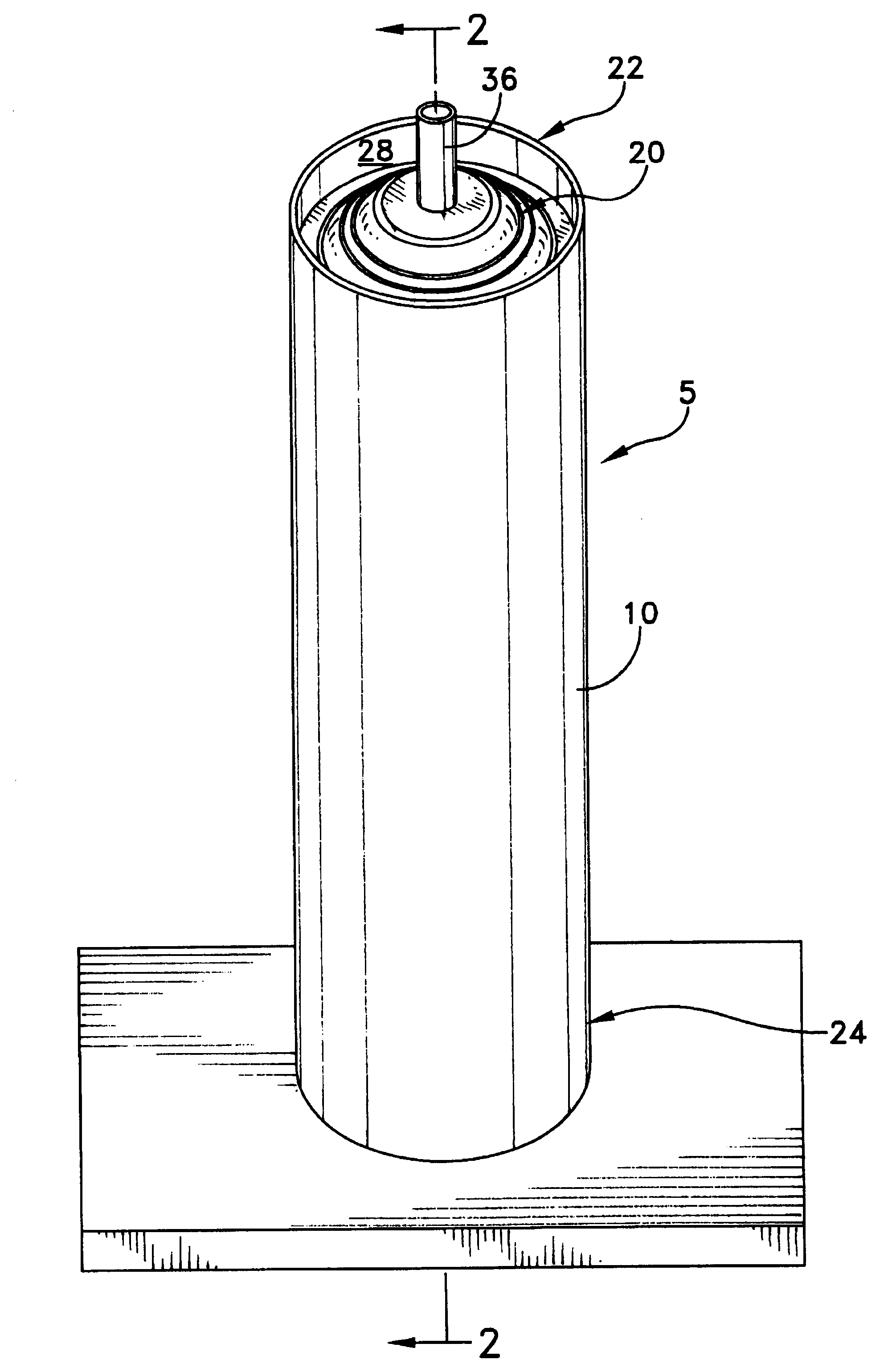
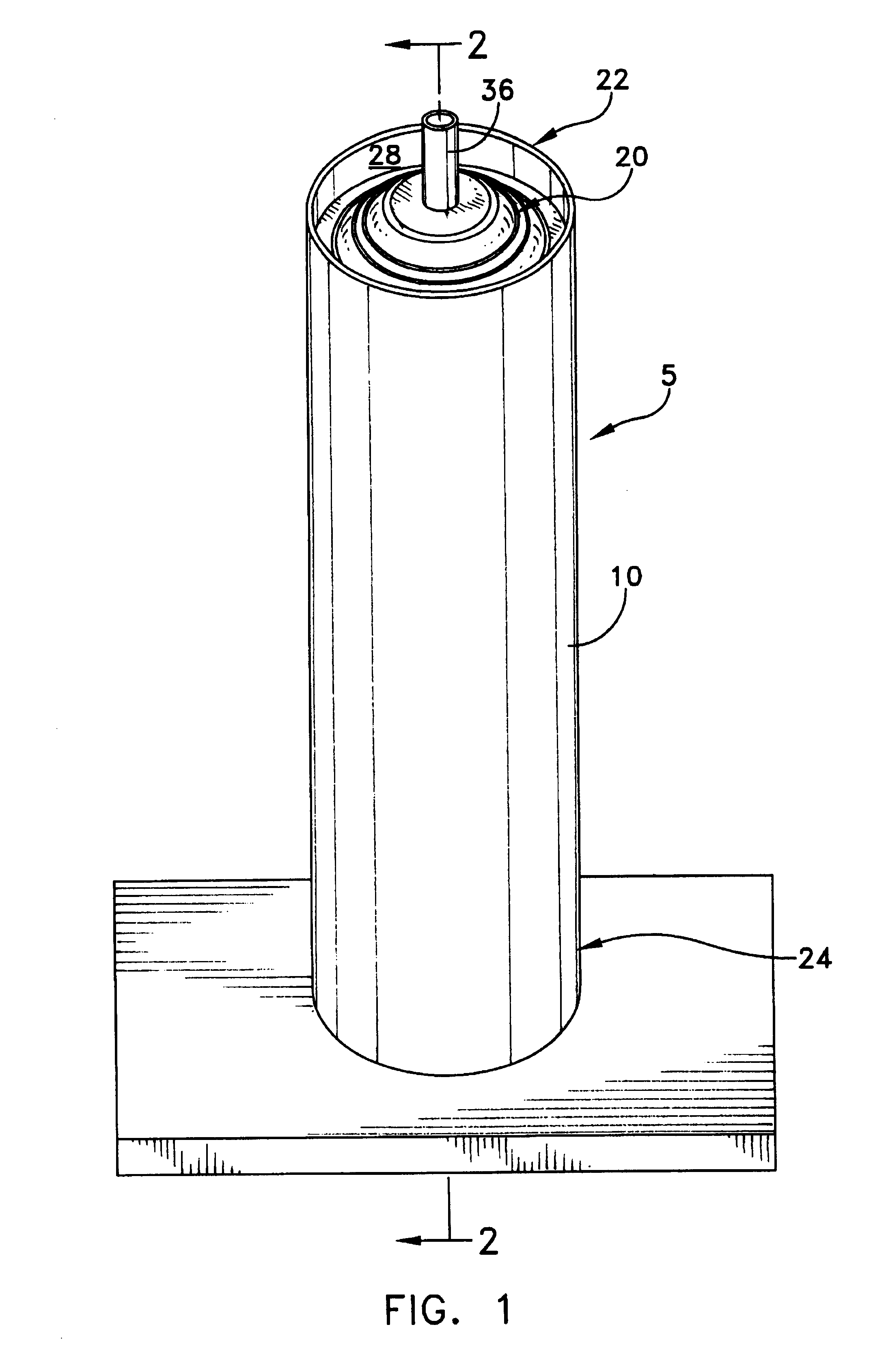
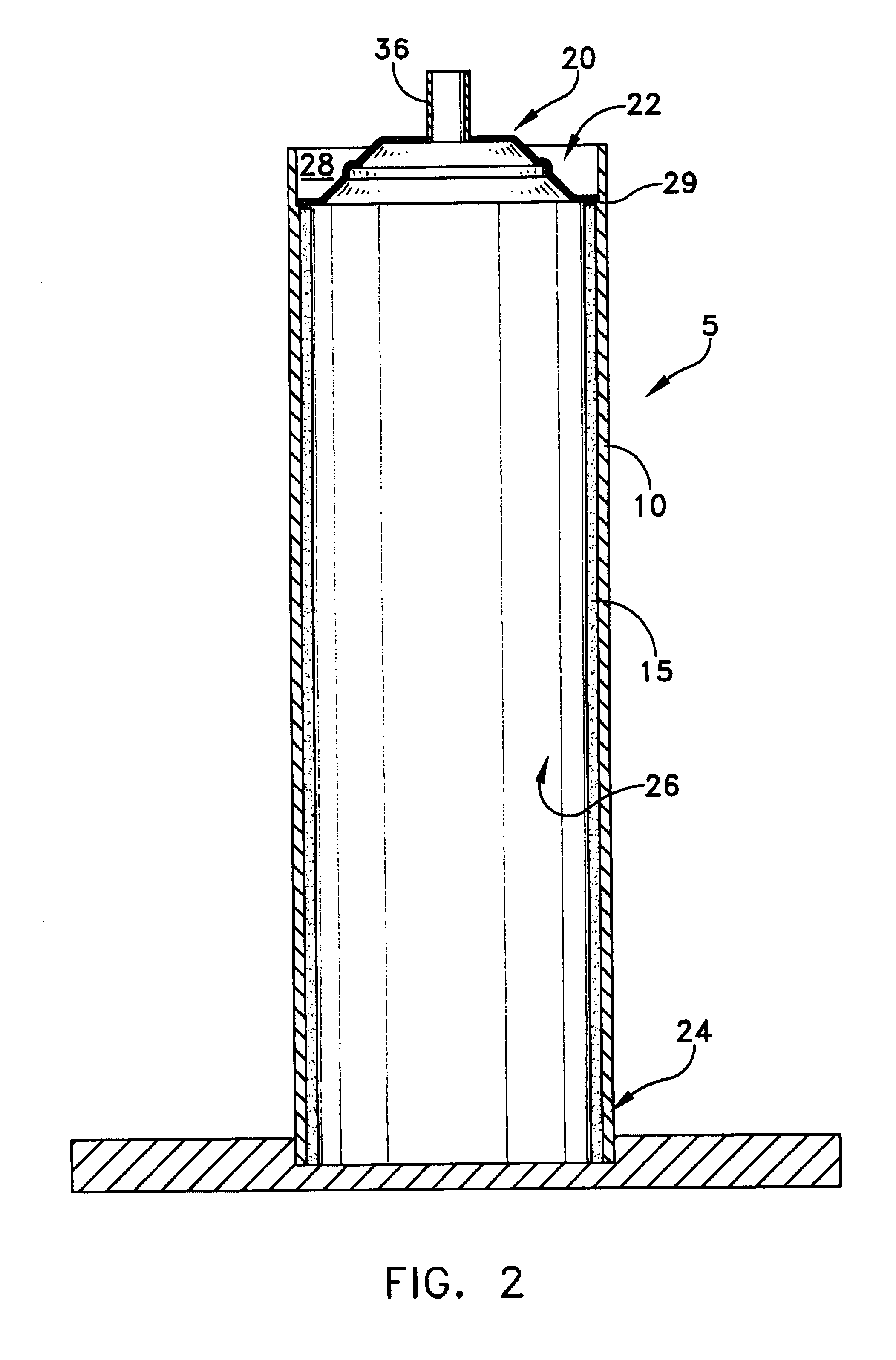
[0020]This description of preferred embodiments is intended to be read in connection with the accompanying drawings, which are to be considered part of the entire written description of this invention. In the description, relative terms such as “horizontal,”“vertical,”“up,”“down,”“top” and “bottom” as well as derivatives thereof (e.g., “horizontally,”“downwardly,”“upwardly,” etc.) should be construed to refer to the orientation as then described or as shown in the drawing figure under discussion. These relative terms are for convenience of description and normally are not intended to require a particular orientation. Terms including “inwardly” versus “outwardly,”“longitudinal” versus “lateral” and the like are to be interpreted relative to one another or relative to an axis of elongation, or an axis or center of rotation, as appropriate. Terms concerning attachments, coupling and the like, such as “connected” and “interconnected,” refer to a relationship wherein structures are secur...


PUM

PropertyMeasurementUnit
thicknessaaaaaaaaaa
stress concentrationaaaaaaaaaa
stress concentratoraaaaaaaaaa

Abstract

A heat pipe is provided having a vessel with a closed first end, a second end, and a wick on an inner surface that defines a passageway. A convex wall is positioned at the second end so as to block the passageway. The convex wall is deformable so as to move from a first position wherein a portion of the wall is convex to a second position wherein the portion of the wall is concave. The convex wall may include at least one stress concentrator so that upon an application of a force to the convex wall, the stress concentrator causes the convex wall to buckle. A method for forming a heat pipe is also provided comprising coating the interior surface of the vessel with a wicking material and partially saturating the wick with a working fluid. The vessel is then partially evacuated. A portion of the vessel is pinched-off so as to seal the vessel. Then, the pinched-off portion of the vessel is pressed so as to move it from a first position wherein the portion is convex to a second position wherein the portion is concave.

Description

CROSS-REFERENCE TO RELATED APPLICATIONS[0001]This application claims priority from co-pending Provisional Patent Application Ser. No. 60 / 356,625, filed Feb. 13, 2002, and entitled DEFORMABLE END CAP FOR HEAT PIPE.FIELD OF THE INVENTION[0002]The present invention generally relates to the manufacture of heat pipes, and more particularly to a method and apparatus for closing the end of a heat pipe after it has been filled with a working fluid.BACKGROUND OF THE INVENTION[0003]As the density and power of electronic components have increased, the problem of excessive heat generation has become a significant concern to industry. Heat pipes have been found to provide superior thermal transfer characteristics for cooling electronic circuits.[0004]In the prior art, a heat pipe often comprises a closed vessel or chamber whose inner surfaces are lined with a porous capillary wick that is saturated with a working fluid. The heat pipe has an evaporator section that absorbs heat and a condenser se...

Claims


Application Information

Patent Timeline
Patent Type & Authority Patents(United States)
IPC IPC(8): B23P6/00B65D59/00B65D51/00B65D51/12F17C11/00F28D15/00F28D15/02
CPCF28D15/0283F28D15/04F28F2220/00Y10T29/49353Y10T29/49377
Inventor CONNORS, MATTHEWGOOD, ARTHUR H.
Owner THERMAL
Why Eureka
Try Eureka