Bumper with integrally formed energy absorber

a technology of energy absorber and bumper, which is applied in the field of bumper systems with integrated energy absorbers and beams, can solve the problems of physical size of energy absorbers, difficult to package and carry at the front of the vehicle, etc., and achieve the effect of reducing the strength requirements, simplifying or eliminating the front end support structure of the vehicle, and simplifying the front end support structur

Inactive Publication Date: 2005-06-21
NETSHAPE INT LLC
View PDF44 Cites 29 Cited by
  • Summary
  • Abstract
  • Description
  • Claims
  • Application Information

AI Technical Summary

Benefits of technology

[0013]An advantage of the present bumper systems is that some of the traditional front-end support structure can be simplified or eliminated. For example, the present inventive bumper system can include an energy absorber with portions that support the front-of-vehicle fascia in areas in front of the vehicle hood. This allows the front end support structure of the vehicle to be simplified, such as by eliminating fascia-supporting struts, by eliminating forwardly-extending flanges on the radiator cross support, by reducing the strength requirements on the radiator cross support and / or by eliminating or reducing strength requirements on a vehicle's front end panel.

Problems solved by technology

Longer bumper strokes with lower initial energy absorption rates have the possibility of satisfying these desires, but this can result in energy absorbers that are physically larger in size than present bumper systems, and that are not easy to package and carry at a front of the vehicle.

Method used


Image

  • Bumper with integrally formed energy absorber
  • Bumper with integrally formed energy absorber
  • Bumper with integrally formed energy absorber

Examples


Embodiment Construction

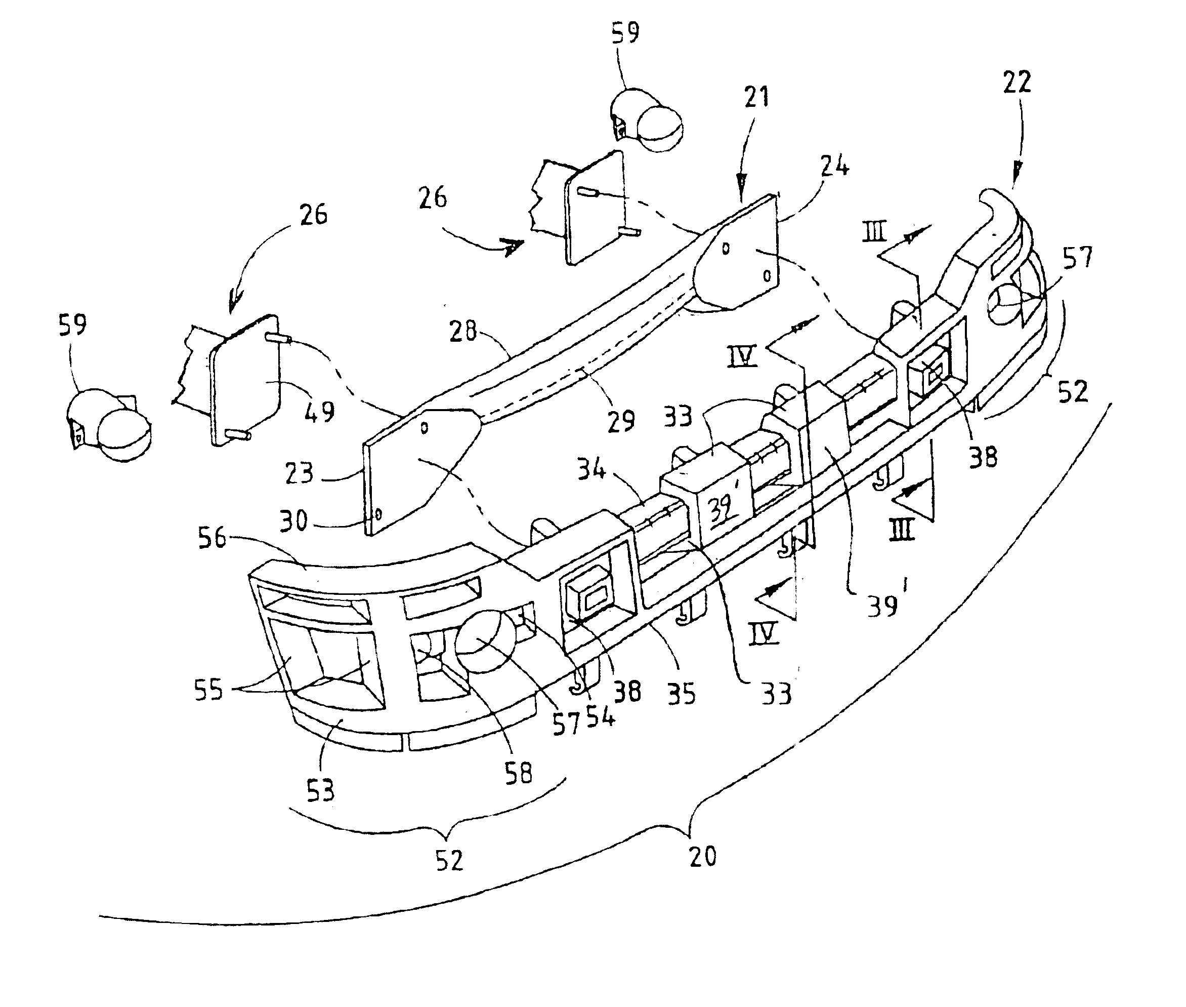
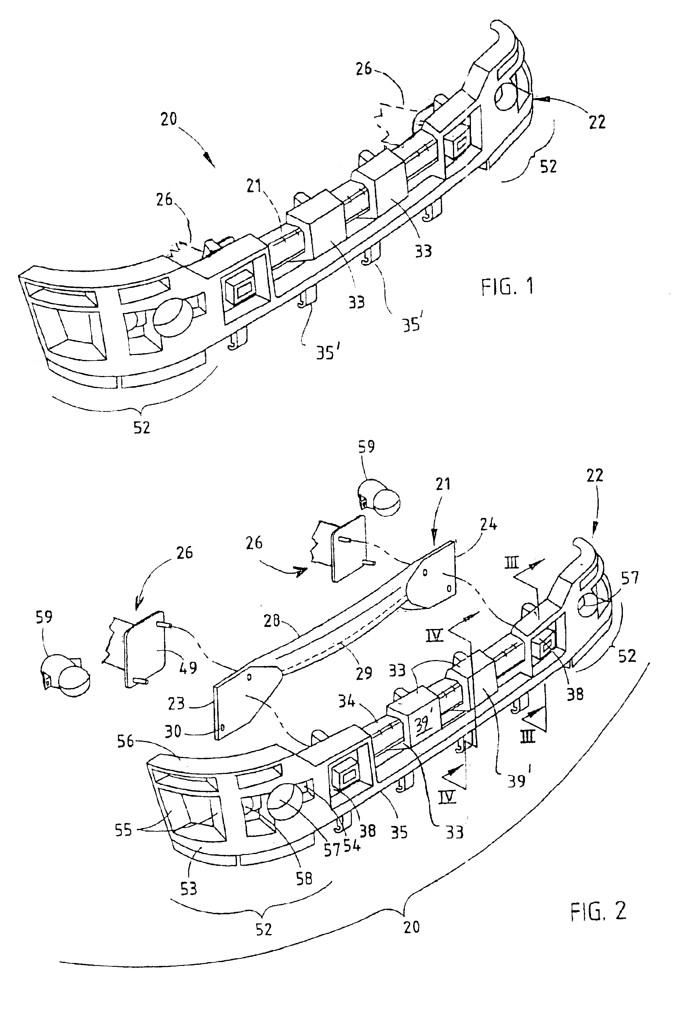
[0025]A bumper system 20 (FIG. 1) includes a beam 21 with a tubular center section and flattened end sections 23 and 24, and a molded energy absorber 22 adapted to nestingly receive the beam 21 to form a unitary subassembly that can be handled and assembled as a unit to a vehicle. The flattened end sections 23 and 24 form vertically enlarged attachment members or “hands” on each end of the beam 21 that engage mating flat surfaces on the energy absorber 22. Mounts 26 abuttingly engage a rear of the flattened end sections 23 and 24, and fasteners 27 extend through the energy absorber 22 and the flattened end sections 23 and 24 to secure the tubular beam 21 and energy absorber 22 to the mounts 26. It is contemplated that the term “mount” as used herein includes a rail extending from a vehicle frame, or similar structural frame component.

[0026]The beam 21 (FIG. 1) is described in sufficient detail below for an understanding of the present invention by persons skilled in this art. Noneth...


PUM


Abstract

A bumper system comprising a metal tubular beam, an energy absorber and mounts. The metal tubular beam has a center section having front, rear, top, and bottom walls. The energy absorber includes a rail having a rear surface with a rearwardly-facing C-shaped recess mateably receiving the tubular beam therein, with the energy absorber being configured to crush and absorb impact energy prior to collapse of the tubular beam. The mounts engage a rear of the metal tubular beam.

Description

CROSS-REFERENCE TO RELATED APPLICATION[0001]This application is a continuation of U.S. patent application Ser. No. 10 / 163,838 entitled BUMPER WITH INTEGRATED ENERGY ABSORBER AND BEAM, which was filed on Jun. 6, 2002, now U.S. Pat. No. 6,663,150.BACKGROUND[0002]The present invention relates to vehicle bumper systems, and more particularly relates to a bumper system having an integrated energy absorber and beam, and also relates to novel beam constructions such as those that are shaped for engagement with mating energy absorbers.[0003]Bumper systems using integrated energy absorber and bumper beam arrangements are desired to improve assembly of bumper systems to vehicles, to minimize the number and types of mechanical fasteners overall, and to simplify tooling. In particular, it is desirable to provide a design where the beam and energy absorber can be assembled off-line of the main vehicle assembly line into a unitary subassembly, and then manipulated as a unit for attachment to the ...

Claims


Application Information

Patent Timeline
Patent Type & Authority Patents(United States)
IPC IPC(8): B60D1/52B60D1/00B60D1/14B60R19/18B60R19/24E02F3/84
CPCB60D1/52B60D1/56B60R19/18E02F3/847B60D1/243E02F3/842B60R19/24B60R2019/1806B60R2019/1826B60R2019/1866B60R2019/188B60R2019/1813
Inventor EVANS, DARIN
Owner NETSHAPE INT LLC
Why Eureka
Try Eureka