
Anti-submarine vehicle seat device

a vehicle seat and anti-submarine technology, applied in the direction of chairs, vehicular safety arrangements, pedestrian/occupant safety arrangements, etc., can solve the problems of increasing the complexity of assembling the seat assembly, and achieve the effect of reliably preventing submarin

Inactive Publication Date: 2005-06-21
NHK SPRING CO LTD
View PDF34 Cites 55 Cited by
  • Summary
  • Abstract
  • Description
  • Claims
  • Application Information

AI Technical Summary

Benefits of technology

[0007]In view of such problems in previous anti-submarine devices, a primary object of the present invention is to provide an anti-submarine vehicle seat device which can reliably prevent submarining without complicating the assembling of the seat assembly.
[0008]A second object of the present invention is to provide an anti-submarine vehicle seat device which can be easily retro-fitted to an existing vehicle seat.
[0009]A third object of the present invention is to provide an anti-submarine vehicle seat device which is economical to produce but which also has adequate mechanical strength to withstand the reaction of the actuator at the time of activation.
[0010]According to the present invention, such objects can be accomplished by providing a subassembly for a vehicle seat device for raising a front part of a seat to prevent a vehicle occupant from slipping forward under a seat belt in an impact situation such as a vehicle crash, comprising: a casing adapted to be attached to a seat frame; a power actuator fixedly secured in the casing; and an arm pivotally supported by the casing, and adapted to be actuated by the power actuator.
[0011]Thus, the subassembly is adapted to be built compact, strong and economical. For instance, the casing may consist of a longitudinally elongated hollow member receiving the actuator therein, and the arm is pivotally attached to a front end of the casing so as to be rotatable around a lateral axial line. For a favorable operation of the device and compact design, the subassembly may further comprise a lock mechanism for keeping the arm substantially at an actuated position once the arm is actuated by the power actuator. Typically, the power actuator comprises a cylinder / piston assembly, and the lock mechanism is provided at an end of a cylinder of the assembly for cooperation with a piston rod extending from the end of the cylinder.

Problems solved by technology

These factors contribute to increasing the complexity of assembling the seat assembly.

Method used


Image

  • Anti-submarine vehicle seat device
  • Anti-submarine vehicle seat device
  • Anti-submarine vehicle seat device

Examples


Embodiment Construction

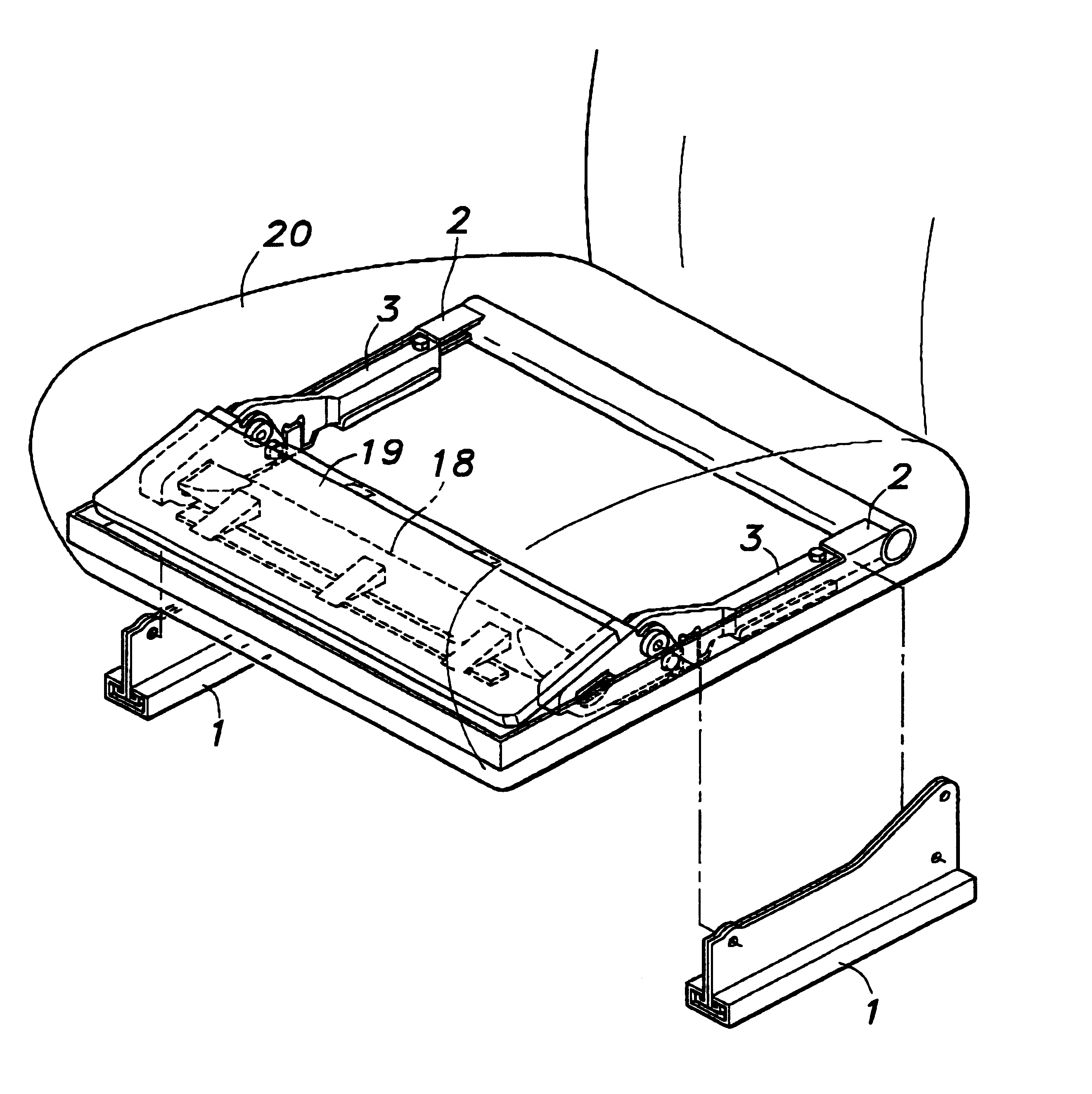
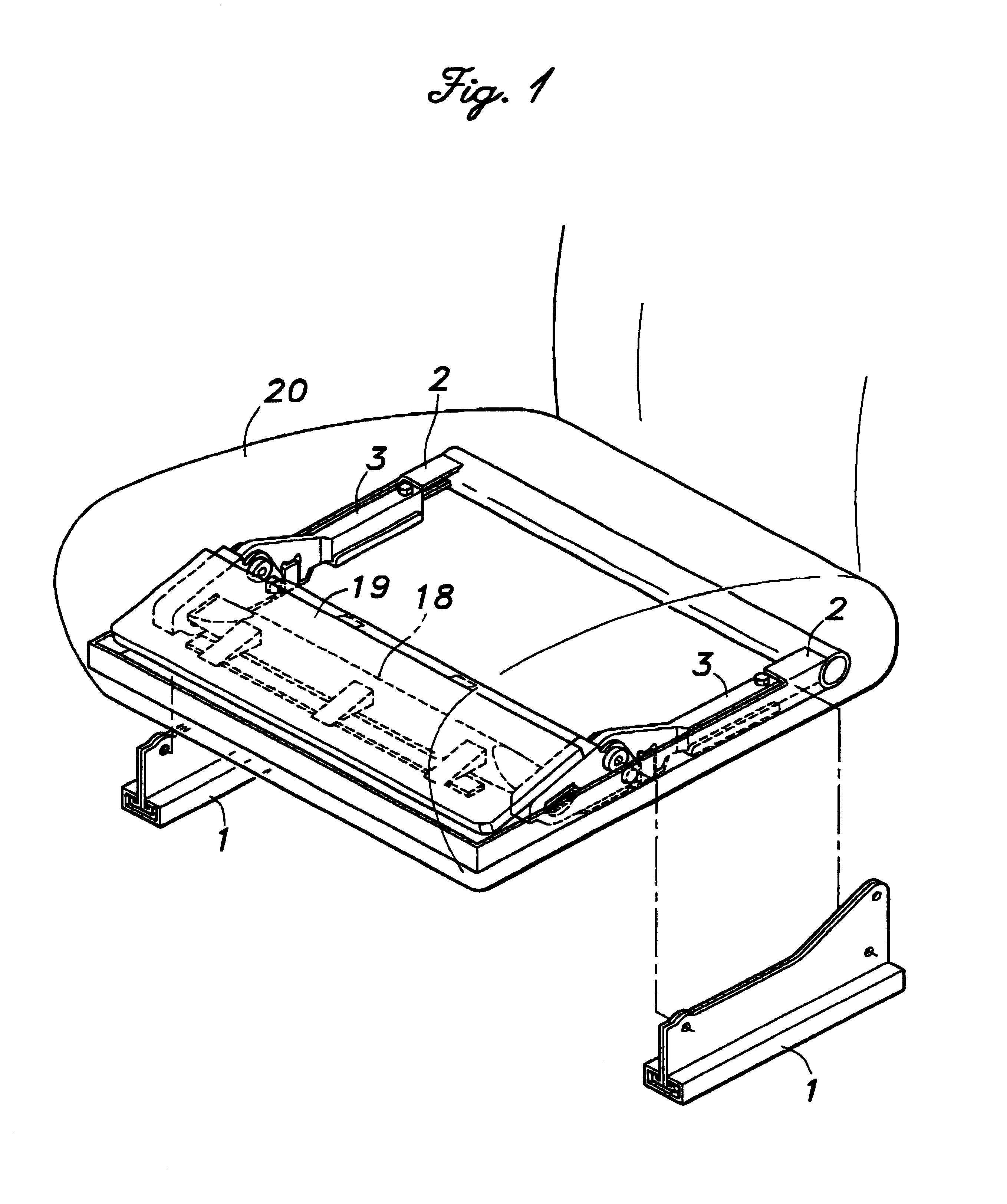
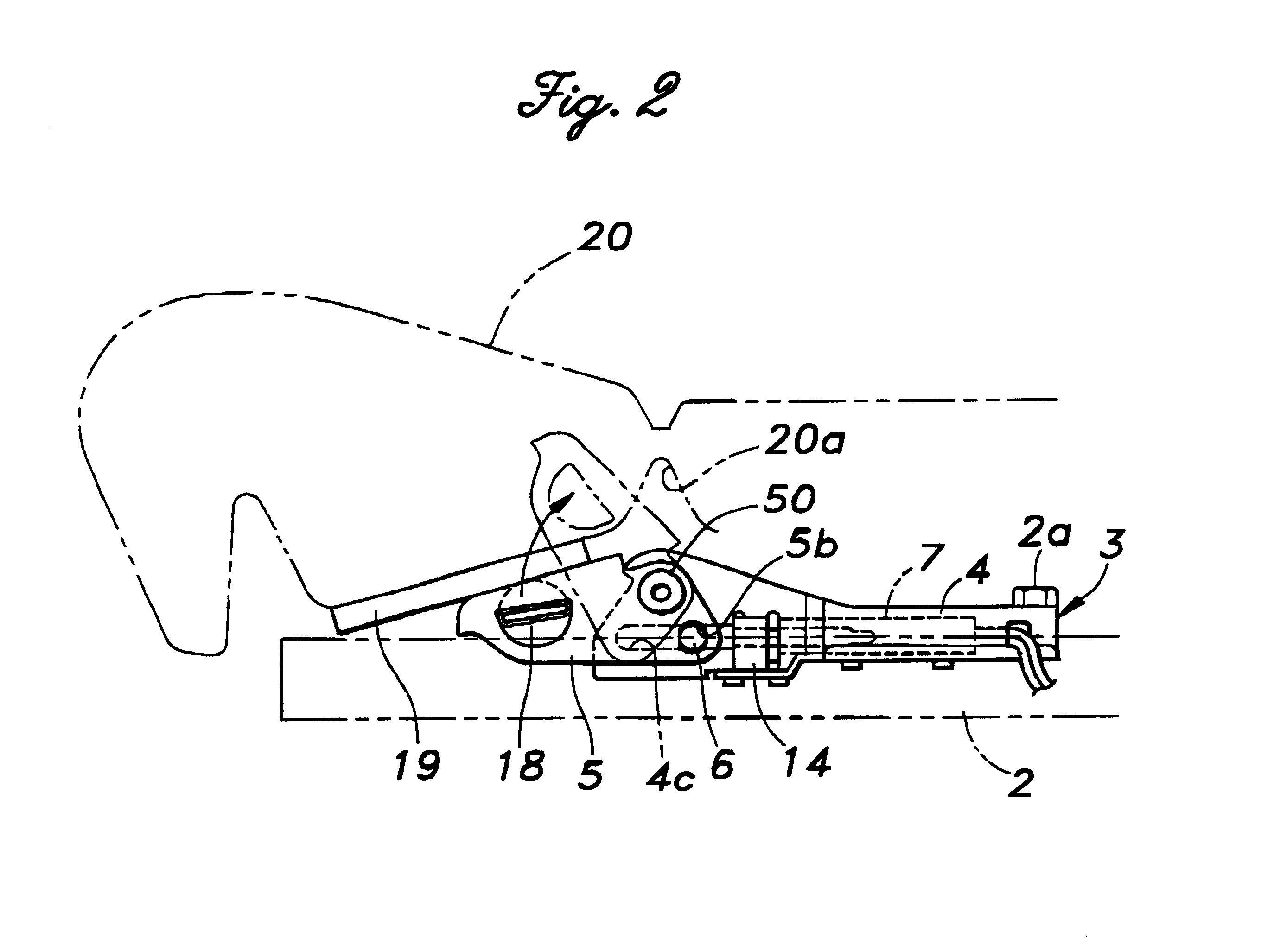
[0019]FIG. 1 is a perspective view of a seat device embodying the present invention, and FIG. 2 is a simplified side view of this device. Seat rails 1 fixed to the vehicle body support a seat frame 2 so as to be slidable in the fore-and-aft direction via holders, and a seat adjustment mechanism not shown in the drawings allows the seat frame 2 to be secured at a desired position. The seat frame 2 is made of a stamped pan-shaped member having upright flanges along the front and both sides thereof, and the rear end of the seat frame is reinforced by a pipe member. A pair of anti-submarine seat device subassemblies 3 are attached to the inner surfaces of the upright side flanges of the seat frame 2 in a symmetric manner.

[0020]FIG. 2 shows the structure of one of the subassemblies 3. Each subassembly 3 comprises a tubular casing 4 having a rectangular cross section, an arm 5 vertically rotatable supported by the front end of the casing 4, via a pivot pin 50, so as to form a part of the ...


PUM


Abstract

Provided is an anti-submarine vehicle seat device which can reliably prevent submarining without complicating the assembling of the seat assembly, and is adapted to be retrofitted. Major parts of the device are incorporated into a subassembly which comprises a casing adapted to be attached to a seat frame, a power actuator fixedly secured in the casing, an arm pivotally supported by the casing, and adapted to be actuated by the power actuator, and a lock mechanism for keeping the arm substantially at an actuated position once the arm is actuated by the power actuator.

Description

CROSS REFERENCE TO RELATED APPLICATIONS[0001]Copending U.S. patent application Ser. No. 09 / 334,116 filed Jun. 15, 1999, and three commonly assigned US patent applications of even date are directed to similar subject matters, and the contents of these applications are incorporated herein by reference.TECHNICAL FIELD[0002]The present invention relates to a vehicle seat device, and in particular to an anti-submarine device which can be installed in a vehicle seat device to prevent a vehicle occupant from slipping forward under the seat belt in case of an impact situation such as a vehicle crash.BACKGROUND OF THE INVENTION[0003]It is known that the so-called submarine phenomenon may occur in an impact situation such as a vehicle crash by the vehicle occupant slipping forward under the seat belt. This is prone to occur when the occupant sits in the front end of the seat or when the back rest is tilted rearward, which reduces the effectiveness of the seat belt in restraining the vehicle o...

Claims


Application Information

Patent Timeline
IPC IPC(8): B60N2/42B60N2/427
CPCB60N2/4221B60N2/42718B60N2/4279B60N2/42781B60N2/42763
Inventor YAMAGUCHI, HIROYOSHISHONO, HAJIME
Owner NHK SPRING CO LTD
Learn More