Method for forming a dielectric spacer in a non-volatile memory device

Active Publication Date: 2005-06-21
MONTEREY RES LLC
View PDF4 Cites 16 Cited by
  • Summary
  • Abstract
  • Description
  • Claims
  • Application Information

AI Technical Summary

Benefits of technology

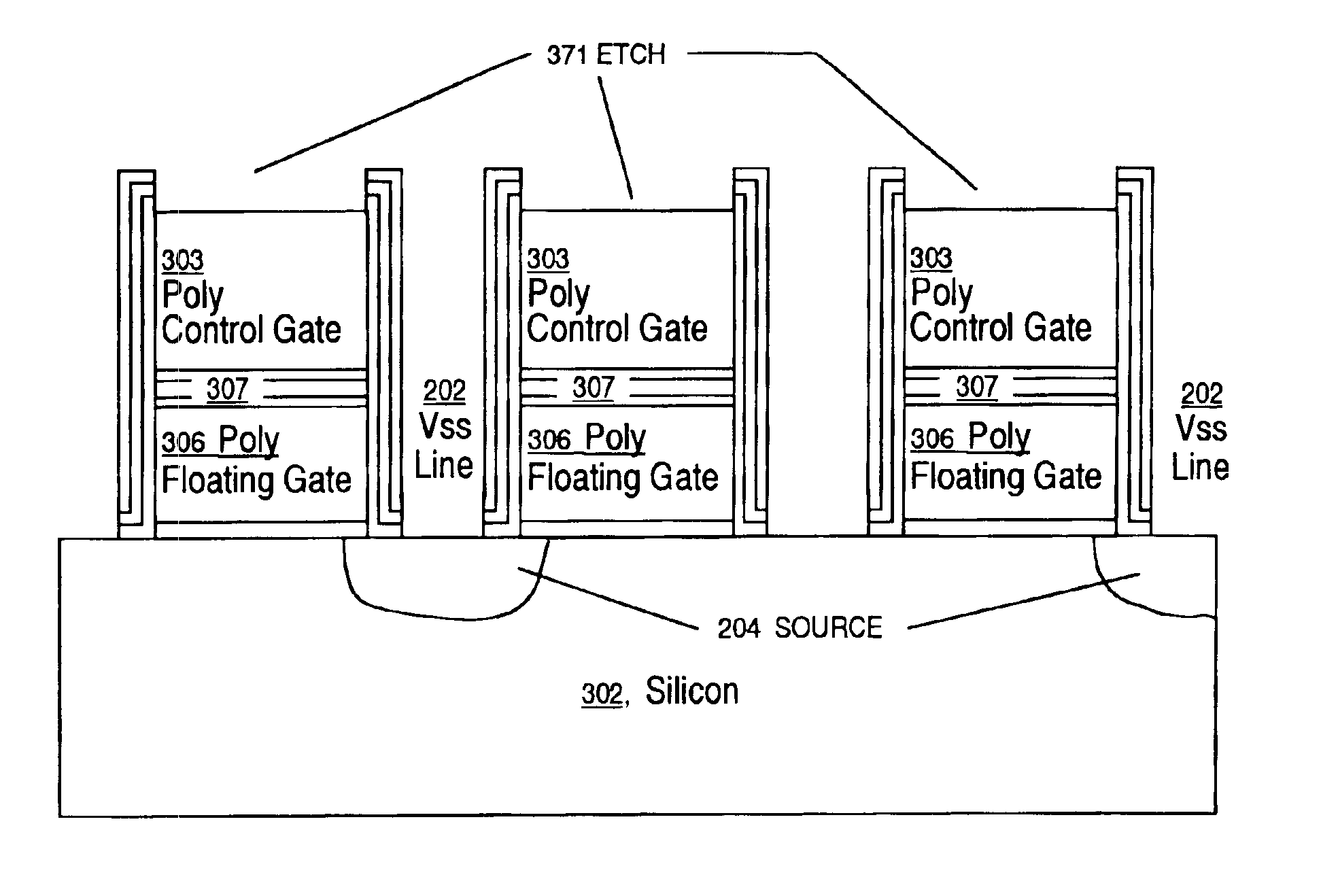
[0011]Accordingly, embodiments of the present invention present a means of reducing the requisite memory device footprint by forming a Vss line above the substrate and STI trenches, thus obviating the need

Problems solved by technology

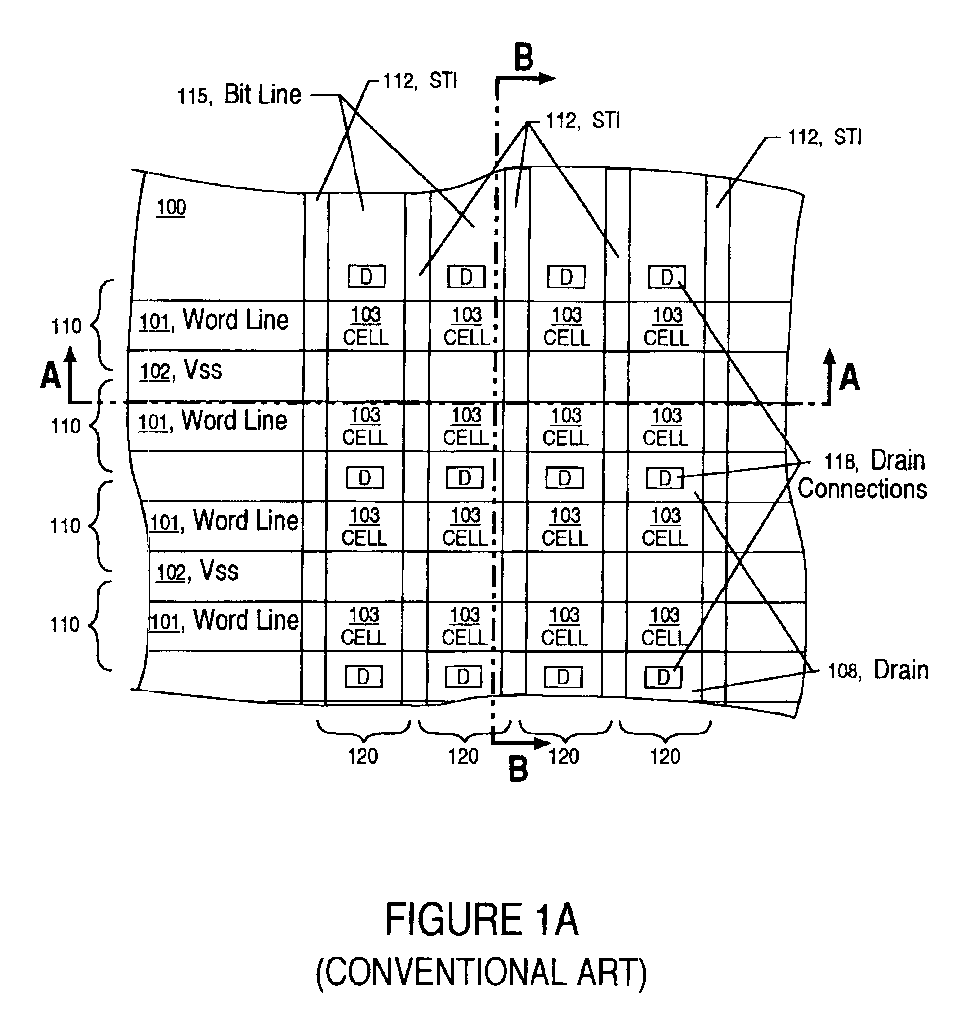
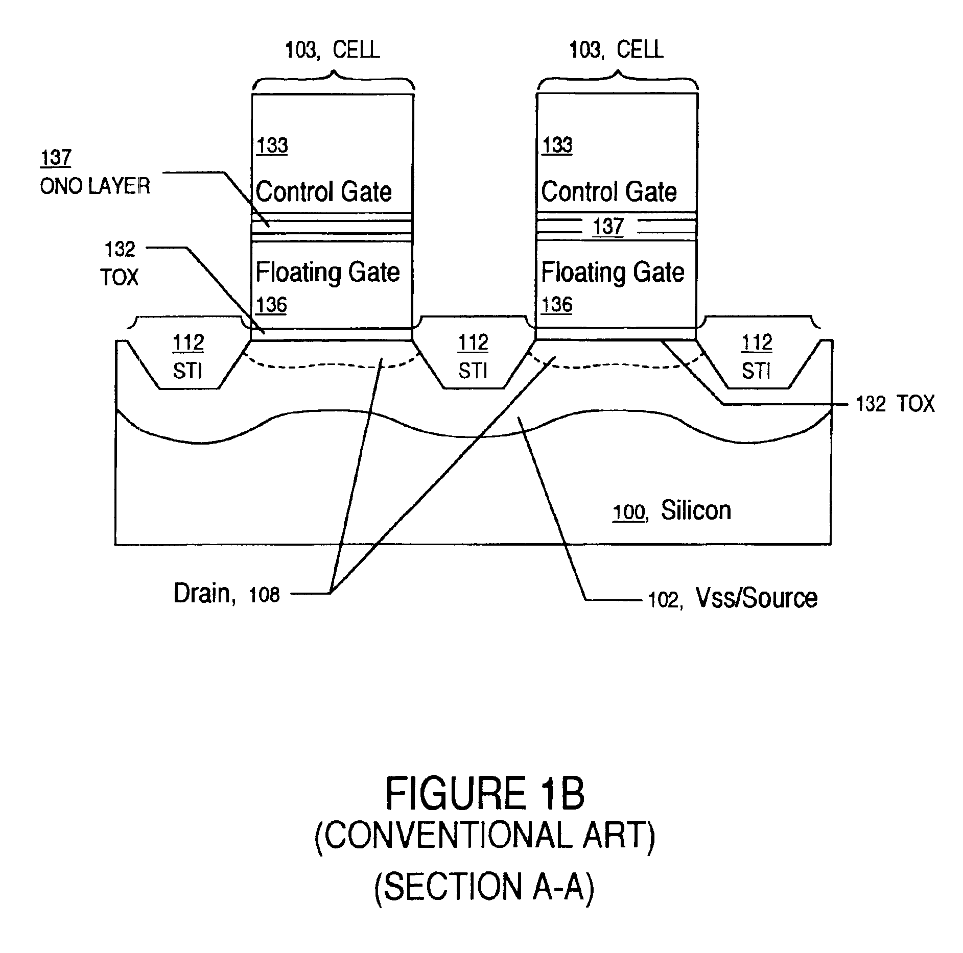
Continued shrinking pushes the limits of physics by putting features in such proxim

Method used


Image

  • Method for forming a dielectric spacer in a non-volatile memory device
  • Method for forming a dielectric spacer in a non-volatile memory device
  • Method for forming a dielectric spacer in a non-volatile memory device

Examples


Embodiment Construction

[0028]Reference will now be made in detail to the preferred embodiments of the invention, examples of which are illustrated in the accompanying drawings. While the invention will be described in conjunction with the preferred embodiments, it will be understood that they are not intended to limit the invention to these embodiments. On the contrary, the invention is intended to cover alternatives, modifications and equivalents, which may be included within the spirit and scope of the invention as defined by the appended claims. Furthermore, in the following detailed description of the present invention, numerous specific details are set forth in order to provide a thorough understanding of the present invention. However, the present invention may be practiced without these specific details. In other instances, well-known methods, procedures, components, and circuits have not been described in detail so as not to unnecessarily obscure aspects of the present invention.

[0029]A planar vie...


PUM


Abstract

Embodiments of the present invention relate to a method for fabricating a Vss line in a memory device, which comprises: forming a plurality of memory cells above a semiconductor substrate, forming a channel between two of the memory cells, forming an oxide/nitride/oxide stack above the memory cells and the channel, removing a portion of the oxide/nitride/oxide stack between the memory cells to expose the semiconductor substrate, removing the oxide/nitride/oxide stack above the gates of the memory cells, forming a plurality of source regions in the substrate between the memory cells, forming a poly-silicon layer above the memory cells and the channel to connect to the source regions, and removing a sufficient portion of the poly-silicon layer to form a Vss line.

Description

FIELD OF THE INVENTION[0001]The present invention relates to the field of semiconductor device manufacture. Specifically, the present invention pertains to a Vss line in a flash memory cell and a method for forming such a line.BACKGROUND OF THE INVENTION[0002]As semiconductor devices continue to become smaller and smaller, new techniques arise in achieving ever decreasing footprints for device functionality. Memory devices, especially, because there are many millions of identical cells in a single memory chip, are the focus of intensive miniaturization efforts.[0003]Modern memory devices are employing characteristic feature sizes approaching 100 nm, with even smaller device sizes on the technology horizon. Continued shrinking pushes the limits of physics by putting features in such proximity that electrical isolation and electrical connection to cells is very difficult.[0004]One of the techniques used to achieve the isolation such miniaturization requires is Shallow Trench Isolation...

Claims


Application Information

Patent Timeline
IPC IPC(8): H01L27/115H01L21/70H01L21/8247H01L21/336H01L21/02
CPCH01L27/115H01L27/11521H01L29/6656H10B69/00H10B41/30
Inventor THURGATE, TIMOTHYWONG, NGA-CHING
Owner MONTEREY RES LLC
Why Eureka
Try Eureka