Wireless communication system, fixed base station and mobile terminal station

a technology of fixed base station and wireless communication, applied in the field of wireless communication system, can solve the problems of reducing communication resources and affecting the realization of broad band data transmission

Inactive Publication Date: 2005-06-21
DENSO CORP +1
View PDF26 Cites 245 Cited by
  • Summary
  • Abstract
  • Description
  • Claims
  • Application Information

AI Technical Summary

Benefits of technology

[0024]FIGS. 14A and 14B show configuration examples of ROF technology with base band sign...

Problems solved by technology

Thus, the application of a cellular communication system to the communication between the a vehicle and a roadside causes a decrease of com...

Method used


Image

  • Wireless communication system, fixed base station and mobile terminal station
  • Wireless communication system, fixed base station and mobile terminal station
  • Wireless communication system, fixed base station and mobile terminal station

Examples


Embodiment Construction

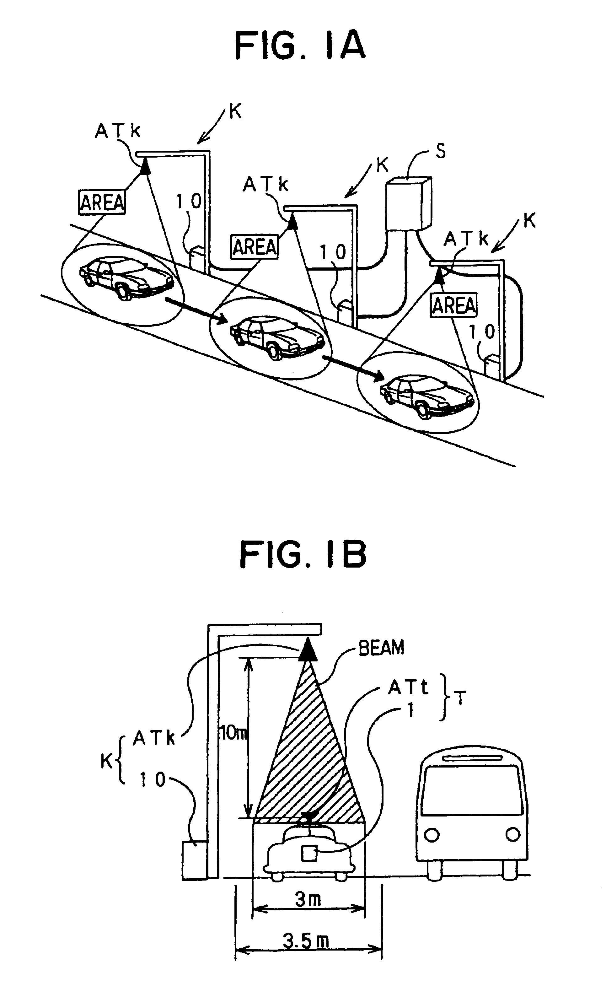
[0026]Referring first to FIGS. 1A and 1B, a communication system comprises a plurality of base stations K fixedly arranged with predetermined distance along a road and a mobile terminal station T mounted in and carried by a vehicle running on the road.

[0027]The terminal station T comprises an antenna (terminal station antenna) ATt installed in the upper part of a vehicle and a terminal station device 1 for wireless communication through the terminal station antenna ATk.

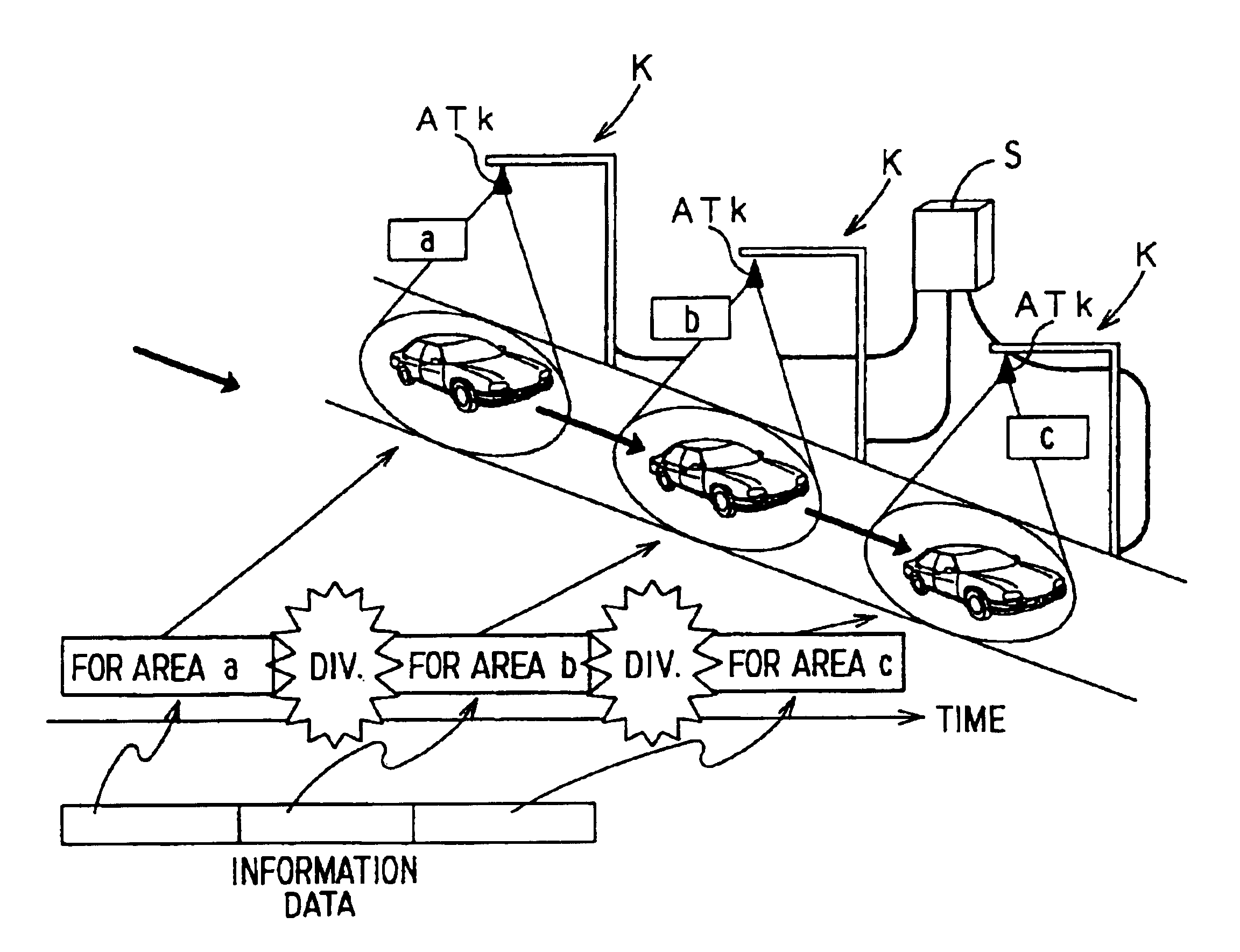
[0028]On the other hand, each base station K comprises an antenna (base station antenna) ATk provided above the road and a base station device 10 for wireless communication through the base station antenna ATk. In addition, the base station devices 10 are connected to a control station S through optical fibers.

[0029]The base station K emits carrier wave beam from the base station antenna ATk to form a predetermined communication area so that radio communication is performed between the terminal station T which entered...


PUM


Abstract

A radio communication system between a mobile terminal station of a vehicle and a plurality of roadside fixed base stations is so constructed that communication areas of the base stations do not overlap with each other and satisfy the following two conditions. Condition (i): each communication area is defined so that there cannot be a plurality of terminal stations simultaneously. Condition (ii): it is needless to perform multiple access such as time division in the communication area and capable of affording the whole band and all the communication time allocated to one communication area to one terminal station and broad band communication becomes possible. Thus, each mobile terminal station can utilize all the frequency band allocated for service.

Description

CROSS REFERENCE TO RELATED APPLICATION[0001]This application is based on and incorporates herein by reference Japanese patent application Ser. No. 2000-72387 filed Mar. 15, 2000.BACKGROUND OF THE INVENTION[0002]The present invention relates to a wireless communication system capable of a broad band package data transmission between mobile terminal stations carried by vehicles and fixed base stations fixedly provided along a traveling route of the vehicles, for example, between vehicles and a roadside.[0003]As a wireless communication technology in the field of mobile communication, cellular communication systems such as PDC (Personal Digital Cellular) have already been realized. In PDC, service area is divided into a lot of wide radio wave zone referred to as a cell which is a macro cell having a radii of 0.5 km-20 km, and a fixed radio base station (BS) is installed in the center of each cell as shown in FIG. 15A. Due to the macro cell structure, only a small number of base station...

Claims


Application Information

Patent Timeline
IPC IPC(8): H04Q7/36H04W16/32
CPCH04W16/32
Inventor AOKI, YUTAKAOKADA, MINORUFUJISE, MASAYUKIHARADA, HIROSHI
Owner DENSO CORP
Why Eureka
Try Eureka